Table of Contents
Advertisement
Quick Links
Manual
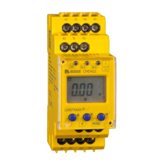
CMD420-DM
CMD421-DM
Current monitoring device with analogue output signal
for monitoring of 3AC currents with current transformer
for overcurrent or undercurrent
or in window mode for overcurrent and undercurrent
Software version CMD420-DM: D287 V1.1x
Software version CMD421-DM: D294 V1.1x
CMD420_421-DM_D00224_01_M_XXEN/08.2016
Advertisement
Table of Contents

Related Manuals for Bender CMD420-DM


Summary of Contents for Bender CMD420-DM
- Page 1 CMD420-DM CMD421-DM Current monitoring device with analogue output signal for monitoring of 3AC currents with current transformer for overcurrent or undercurrent or in window mode for overcurrent and undercurrent Software version CMD420-DM: D287 V1.1x Software version CMD421-DM: D294 V1.1x CMD420_421-DM_D00224_01_M_XXEN/08.2016...
- Page 2 Bender GmbH & Co. KG P.O. Box 1161 • 35301 Gruenberg • Germany Londorfer Strasse 65 • 35305 Gruenberg • Germany Tel.: +49 6401 807-0 • Fax: +49 6401 807-259 E-Mail: info@bender.de • www.bender.de © Bender GmbH & Co. KG All rights reserved.
-
Page 3: Table Of Contents
Table of Contents 1. Important information ..................7 How to use this manual ................. 7 Technical support: service and support ........... 8 1.2.1 First level support ..................... 8 1.2.2 Repair service ..................... 8 1.2.3 Field service ......................9 Training courses ..................... 10 Delivery conditions .................. - Page 4 Table of Contents 3.2.9 Menu item AnA for interface configuration ........18 3.2.10 Password protection (on, OFF) ..............19 3.2.11 Factory setting FAC ..................19 3.2.12 Transformation ratio of the current transformers ......19 4. Installation, connection and commissioning ........... 21 Installing the device ..................
- Page 5 Table of Contents 6. Technical data ....................41 Data in tabular form ..................41 Current and voltage curves of the analogue interface ....46 Standards, approvals and certifications ..........47 Label for modified versions ............... 47 Ordering details ..................... 48 INDEX ........................
-
Page 7: Important Information
1. Important information 1.1 How to use this manual This manual is intended for qualified personnel working in electrical engineering and electronics! Always keep this manual within easy reach for future reference. To make it easier for you to understand and revisit certain sections in this man- ual, we have used symbols to identify important instructions and information. -
Page 8: Technical Support: Service And Support
Important information This manual has been compiled with great care. It might nevertheless contain errors and mistakes. Bender cannot accept any liability for injury to persons or damage to property resulting from errors or mistakes in this manual. 1.2 Technical support: service and support For commissioning and troubleshooting Bender offers you: 1.2.1... -
Page 9: Field Service
Important information Bender GmbH, Repair-Service, Londorfer Str. 65, 35305 Gruenberg 1.2.3 Field service On-site service for all Bender products Commissioning, configuring, maintenance, troubleshooting of Bender products Analysis of the electrical installation in the building (power quality test, ... -
Page 10: Training Courses
ZVEI (Zentralverband Elektrotechnik- und Elektronikindustrie e. V.) (German Electrical and Electronic Manufacturer's Association) also applies. Sale and delivery conditions can be obtained from Bender in printed or elec- tronic format. 1.5 Inspection, transport and storage Inspect the dispatch and equipment packaging for damage, and compare the contents of the package with the delivery documents. -
Page 11: Warranty And Liability
Important information 1.6 Warranty and liability Warranty and liability claims in the event of injury to persons or damage to property are excluded if they can be attributed to one or more of the follow- ing causes: Improper use of the device. ... -
Page 12: Disposal
13 August 2005 must be taken back by the manufacturer and disposed of properly. For more information on the disposal of Bender devices, refer to our homepage at www.bender-de.com -> Service & support. -
Page 13: Safety Instructions
2. Safety instructions 2.1 General safety instructions Part of the device documentation in addition to this manual is the enclosed "Safety instructions for Bender products". 2.2 Work activities on electrical installations Only qualified personnel are permitted to carry out the work necessary to install, commission and run a device or system. -
Page 14: Intended Use
Safety instructions 2.3 Intended use The current monitoring device CMD420-DM resp. CMD421-DM monitors three-phase or also three different single-phase AC systems for undercurrent or overcurrent, undercurrent and overcurrent with window discriminator function. For current measurement, three external standard current transfor- mers are to be connected according to the wiring diagram. -
Page 15: Function
monitoring with window discriminator function Current monitoring using standard current transformers: x/ 1A (CMD420-DM), x/ 5A (CMD421-DM) 1 analogue output signal available as standardised current or voltage Digital measured value display via multi-functional LC display ... -
Page 16: Window Discriminator Function
Function or falls below the release value (response value plus hysteresis), the alarm LEDs go out. With the fault memory activated, the alarm relays do not change their actual state until the reset button R is pressed. 3.2.1 Window discriminator function This operating can be used to monitor the measured current for two response values overcurrent and undercurrent. -
Page 17: Malfunction
"out" menu. A certain output is permanently assigned to the signal selec- ted from the menu, only this output may be wired: Output signal Terminal Purpose of use Current output for Bender measuring instru- DC 0…400 μA μA ments of the 96.. series. Standardised current output with selectable DC 0/4…20 mA... -
Page 18: Menu Item Ana For Interface Configuration
Function 3.2.9 Menu item AnA for interface configuration Display Measured variable 100-% value CMD420-DM maximum current > L1L2L3 I 0.30 A adjustable from 0.1…1 A x n from L1,L2 or L3 minimum current < L1L2L3 I 0.30 A adjustable from 0.1…1 A x n from L1,L2 or L3 L1 I 0.30 A... -
Page 19: Password Protection (On, Off)
3.2.12 Transformation ratio of the current transformers The transformation ratio for the current transformers has to be set as factor n in the menu "Set". CMD420-DM requires current transformers with a transformation ratio of n = x/1A. CMD421-DM requires current transformers with a transformation ratio of n = x/5A. - Page 20 Adjustable response value = nominal response range x factor n If the calculation of the adjustable response value results in a value of more than three digits, the first three digits indicated are not rounded. Response value range CMD420-DM Factor min.
-
Page 21: Installation, Connection And Commissioning
4. Installation, connection and commissioning Only qualified personnel are permitted to carry out the work necessary to install, commission and run a device or system. Risk of electrocution due to electric shock! Touching live parts of the system carries the risk of: An electric shock ... -
Page 22: Connection Of The Device
Installation, connection and commissioning Mounting on DIN rail: Snap the rear mounting clip of the device into place in such a way that a safe and tight fit is ensured. Screw fixing: Use the tool to move the rear mounting clips (a second. mounting clip is re- quired, see ordering information) to a position that it projects beyond the en- closure. -
Page 23: Commissioning
Installation, connection and commissioning Connect the conductor to the push-wire ter- minals according to the schematic diagram. Terminal Connections A1, A2 Connection to supply voltage k1, l1 Connection to the conduc- tors to be monitored using k2, l2 current transformers k3, l3 (common) positive pole of the analogue interface... -
Page 24: Factory Setting
Response value overcurrent I1 (prewarning) 0.75 A (50 % of I2) Response value overcurrent I2 (alarm) 1.50 A 100-% value of the analogue output I > 1.50 A CMD420-DM / CMD421-DM Hysteresis: 15 % Fault memory M: activated (on) Analogue interface type 0…20 mA... -
Page 25: Operation And Configuration
5. Operation and configuration 5.1 Display elements in use Display elements in use Element Mode Values of the measurement inputs L1, L2, k1/l1, k2/l2, k3/l3 Transformation ratio factor for external current transformer Undercurrent I1 or I2 < I12 Overcurrent I1 or I2 >... -
Page 26: Function Of The Operating Elements
Operation and configuration 5.2 Function of the operating elements Device front Mode Element Power On LED, green LED Alarm 1 lit up (yellow): Response value 1 reached LED Alarm 2 lit up (yellow): Response value 2 reached Transformation ratio n > 1; AL1 AL2 I = 1.6 A = value across the measure- 1.6 A... -
Page 27: Menu Structure
Operation and configuration 5.3 Menu structure All adjustable parameters are listed in the columns "Menu" and "Adjustable parameters". A display-like representation is used to illustrate the parameters in the column Menus. The 100-% value of the analogue output can be chan- ged in the submenu AnA. - Page 28 Operation and configuration Menu Activati Menu Adjustable parameter Menu item Selectable parameters: Hi= overcurrent, (device I 12 In = window function, control) Lo = undercurrent Transformation ratio factor external current transfor- Set parameters via pass- word Factory setting visual inspection Function locked Display software version History memory for the first...
-
Page 29: Display In Standard Mode
Operation and configuration 5.4 Display in standard mode By default, the currently measured current of measuring channel L1 is dis- played. By pressing the Down button the following values can be queried con- secutively: – Current of measuring channel L2 –... -
Page 30: Display In Menu Mode
Operation and configuration 5.5 Display in menu mode 5.5.1 Parameter query and setting: overview Menu Adjustable parameter item Response value query and setting: – Alarm I2 (AL2), (undercurrent, overcurrent or window function can be set in the SEt/I menu) – Prewarning I1 (AL1), (X % of I2) –... - Page 31 Operation and configuration Menu structure t >1,5 s t > 1,5 s t < 1,5 s t < 1,5 s t > 1,5 s CMD420_421-DM_D00224_01_M_XXEN/08.2016...
-
Page 32: Changeover From Overcurrent To Undercurrent Mode Or To Window
Operation and configuration Parameter settings An example is given below on how to change the alarm response value for overcurrent > I1. It is presumed that the option overcurrent (HI) has been se- lected in the SEt/I menu (factory setting). Proceed as follows: 1. -
Page 33: Response Value Setting For Overcurrent
Operation and configuration 5.5.3 Response value setting for overcurrent: - Response value I2 (overcurrent) - Response value I1 (overcurrent) - Hysteresis (Hys) of the response values I1, I2 Increasing the response value I2 (Example: overcurrent) Increasing the response value I1 (prewarning overcurrent) Setting the hysteresis of the response value CMD420_421-DM_D00224_01_M_XXEN/08.2016... -
Page 34: Setting The Fault Memory To Con Mode
Operation and configuration 5.5.4 Setting the fault memory to con mode 5.5.5 Selecting the type of analogue interface Select analogue interface I = 4…20 mA >1,5 s Select analogue interface U = 0…10 V CMD420_421-DM_D00224_01_M_XXEN/08.2016... -
Page 35: Set The 100-% Reference For The Analogue Interface
I2 () (AL) or to a freely configurable value. Factory setting = value related to the highest freely configurable current of L1, L2 or L3 with 0.30 A (CMD420-DM) resp. 1.5 A (CMD421-DM). The freely configurable values for CMD420-DM are between 0.1 and 1 A, for CMD421-DM between 0.5 and 5 A. -
Page 36: Setting The Start-Up Delay T
Operation and configuration 5.5.7 Setting the start-up delay You can set a start-up delay t (0…300 s) for device start. >1,5 s 5.5.8 Changing from overcurrent operation to window operation Use this menu item to set whether the response values of the device apply to overcurrent (HI) or undercurrent operation (Lo). -
Page 37: Setting The Transformation Ratio For External Current Transformer
Operation and configuration 5.5.9 Setting the transformation ratio for external current transformer >1,5 s CMD420_421-DM_D00224_01_M_XXEN/08.2016... -
Page 38: Factory Setting And Password Protection
Operation and configuration 5.5.10 Factory setting and password protection This menu can be used to activate password protection, to modify the pass- word or to deactivate password protection. It is also where the device can be reset to the factory settings. a) Activating the password protection >1,5 s b) Changing the password... -
Page 39: Restoring Factory Settings
Operation and configuration c) Deactivating the password protection >1,5 s 5.5.11 Restoring factory settings ..CMD420_421-DM_D00224_01_M_XXEN/08.2016... -
Page 40: Device Information Query
Operation and configuration 5.5.12 Device information query This function is used to query the software version (1.xx). After activating this function, data will be displayed as a scrolling text. Once one pass is completed you can select individual data sections using the Up/Down buttons.. -
Page 41: Technical Data
Basic insulation between:............... (k1, l1, k2, l2, k3, l3) - (A1, A2), (M+, μA, mA, V) Voltage test acc. to IEC 61010-1 ......................... 2.21 kV Supply voltage CMD420-DM-D-1, CMD421-DM-D-1: ..........................Supply voltage U ......................AC 16…72 V / DC 9.6…94 V Frequency range U ............................. - Page 42 Technical data Response values CMD420-DM Undercurrent Lo < I (Alarm 2) n = 1 ..................AC 0.1…1 A (0.3 A)* Undercurrent Lo < I (Alarm 1) n = 1 ..................100…200 % (150 %)* ..................Take a maximum nominal current of 1 A into consideration! Overcurrent Hi >...
- Page 43 Technical data Time response Start-up delay t..........................0…300 s (0.5 s)* Resolution of setting t (0…10 s) .......................... 0.1 s Resolution of setting t (10…99 s) .......................... 1 s Resolution of setting t (100…300 s) ........................10 s Operating time t ............................
- Page 44 Technical data Environment/EMC EMC................................IEC 61326-1 Operating temperature ........................... -25…+55 ºC Classification of climatic conditions acc. to IEC 60721:....................Stationary use (IEC 60721-3-3)............3K5 (except condensation and formation of ice) Transportation (IEC 60721-3-2) ............2K3 (except condensation and formation of ice) Storage (IEC 60721-3-1) ..............
- Page 45 Technical data DIN rail mounting acc. to..........................IEC 60715 Screw fixing ......................... 2 x M4 with mounting clip Software version CMD420-DM ........................D287 V1.1x Software version CMD421-DM ........................D294 V1.1x Weight ................................≤ 150 g ( )* = factory setting CMD420_421-DM_D00224_01_M_XXEN/08.2016...
-
Page 46: Current And Voltage Curves Of The Analogue Interface
Technical data 6.2 Current and voltage curves of the analogue interface Current output 0/4…20 mA Current output 0…400 μA Voltage output 0…10 V CMD420_421-DM_D00224_01_M_XXEN/08.2016... -
Page 47: Standards, Approvals And Certifications
Technical data 6.3 Standards, approvals and certifications 6.4 Label for modified versions There will only be a label in this field, if the device is different from the standard version. CMD420_421-DM_D00224_01_M_XXEN/08.2016... -
Page 48: Ordering Details
Technical data 6.5 Ordering details Response Supply voltage U Device type Art. No. value CMD420-DM-1 AC 16…72 V (push-wire DC 9.6 V…94 V 0.1…1 A x n B73060010 terminals) DC, 15…460 Hz AC 16…72 V CMD420-DM-1 DC 9.6 V…94 V 0.1…1 A x n... -
Page 49: Index
INDEX Adjustable parameters, list 27 LED Alarm 1 lights 26 Automatic self test 16 LED Alarm 2 lights 26 Deleting the fault alarms 26 Malfunction 17 Description of function 15 Device features 15 Manual self test 16 Display elements in use 25 Menu Display in standard mode 29 - AL (response values) 27... - Page 50 - Changeover from overcurrent opera- tion to window operation 36 - Response value setting 33 - Setting time delays 36 Password protection 19 Reset button 26 Response value setting - Hysteresis 33 - Overcurrent (> I) 33 Select analogue interface 34 Service 8 Set the analogue interface 35 Starting the menu mode 26...
- Page 52 Bender GmbH & Co. KG P.O. Box 1161 • 35301 Gruenberg • Germany Londorfer Strasse 65 • 35305 Gruenberg • Germany Tel.: +49 6401 807-0 • Fax: +49 6401 807-259 E-Mail: info@bender.de • www.bender.de BENDER Photos: Bender archives...
Need help?
Do you have a question about the CMD420-DM and is the answer not in the manual?
Questions and answers