Sign In
Upload
Download
Table of Contents
Contents
Add to my manuals
Delete from my manuals
Share
URL of this page:
HTML Link:
Bookmark this page
Add
Manual will be automatically added to "My Manuals"
Print this page
×
Bookmark added
×
Added to my manuals
Manuals
Brands
INGENIA Manuals
Servo Drives
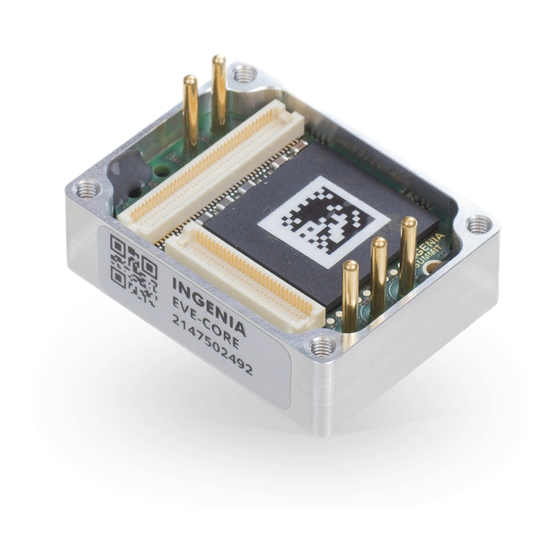
Everest CORE
Product manual
INGENIA Everest CORE Product Manual
Hide thumbs
Also See for Everest CORE
:
Product manual
(58 pages)
1
Table Of Contents
2
3
4
5
6
7
8
9
10
11
12
13
14
15
16
17
18
19
20
21
22
23
24
25
26
27
28
29
30
31
32
33
34
35
36
37
page
of
37
Go
/
37
Contents
Table of Contents
Bookmarks
Table of Contents
1 Table of Contents
2 General Information
Manual Revision History
Disclaimers and Limitations of Liability
Contact
3 Safety Information
For Your Safety
Warnings
Precautions
Pour Votre Sécurité
Avertissements
Précautions
4 Product Description
Part Numbering
Specifications
Electrical and Power Specifications
Motion Control Specifications
Inputs/Outputs and Protections
Communication for Operation
Environmental Specifications
Reliability Specifications
Mechanical Specifications
Compliance
Thermal and Power Specifications
Standby Power Consumption
Thermal Model
Current Derating
Heat Dissipation and Heatsink Calculation
Energy Efficiency
5 Pinout
Connectors Overview
P1 and P2 Power Pins
P3 Feedback Connector
P4 Everest CORE Interface Connector
6 Safe Torque off (STO)
Safety Function Specifications
Integration Requirements
STO External Diagnostic Test
Advertisement
Quick Links
Download this manual
Everest CORE - Product manual
Edition 04/23/2021
For the most up to date information visit the online manual.
INGENIA-CAT S.L.
AVILA 124
08018 BARCELONA
Table of
Contents
Previous
Page
Next
Page
1
2
3
4
5
Advertisement
Table of Contents
Need help?
Do you have a question about the Everest CORE and is the answer not in the manual?
Ask a question
Questions and answers
Related Manuals for INGENIA Everest CORE
Computer Hardware INGENIA Everest CORE Product Manual
(58 pages)
Servo Drives INGENIA Everest XCR Product Manual
(26 pages)
Servo Drives INGENIA Everest XCR Product Manual
(63 pages)
Servo Drives INGENIA EVE-CORE Product Manual
(37 pages)
Servo Drives INGENIA Earth EAR-3/40-C-P Product Manual
(16 pages)
Servo Drives INGENIA Triton Core Product Manual
(42 pages)
Servo Drives INGENIA Jupiter JUP-20/80 Installation Manual
(307 pages)
Servo Drives INGENIA HYD-4/48-S Product Manual
Hydra servo drive (68 pages)
Servo Drives INGENIA Pluto Product Manual
(88 pages)
Servo Drives INGENIA Neptune Product Manual
(90 pages)
Servo Drives INGENIA Nix series Product Manual
(124 pages)
Servo Drives INGENIA TITAN GO Product Manual
(108 pages)
Servo Drives INGENIA Titan GO Product Manual
(41 pages)
Servo Drives INGENIA Triton Go Product Manual
(119 pages)
This manual is also suitable for:
Eve-core
Eve-core-e
Eve-e-core
Table of Contents
Print
Rename the bookmark
Delete bookmark?
Delete from my manuals?
Login
Sign In
OR
Sign in with Facebook
Sign in with Google
Upload manual
Upload from disk
Upload from URL


Need help?
Do you have a question about the Everest CORE and is the answer not in the manual?
Questions and answers