
Related Manuals for INGENIA Triton Core


Summary of Contents for INGENIA Triton Core
- Page 1 TRITON CORE Product Manual Edition 2021-07-07 16:23:18 For the most up to date information visit the online manual. INGENIA-CAT, S.L. C/ Avila 124, 2-B 08018 Barcelona...
-
Page 2: Table Of Contents
Power and operation signalling LED outputs ....................33 CAN signalling LED outputs (only TRI-x/48-C-P)..................... 33 EtherCAT signalling LED outputs (only TRI-x/48-E-P) ..................35 Product Dimensions and Assembly Triton Core with CAN (TRI-x/48-C-P) ....................... 37 Triton Core with EtherCAT (TRI-x/48-E-P)....................... 38 Assembly Instructions............................39 7.3.1 Electrical assembly and ESD precautions....................... - Page 3 Application Software Configuration ..............................41 Applications..............................41 Arduino ................................41 Service...
-
Page 4: General Information
The information contained within this document contains proprietary information belonging to INGENIA-CAT S.L.. Such information is supplied solely for the purpose of assisting users of the product in its installation. INGENIA-CAT S.L. rejects all liability for errors or omissions in the information or the product or in other documents mentioned in this document. ... -
Page 5: Safety Information
TRITON CORE Product Manual | Safety Information 3 Safety Information About this manual Read carefully this chapter to raise your awareness of potential risks and hazards when working with the Triton Servo Drive. To ensure maximum safety in operating the Triton Servo Drive, it is essential to follow the procedures included in this guide. -
Page 6: Product Description
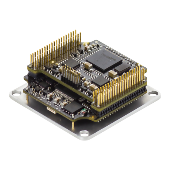
TRITON CORE Product Manual | Product Description 4 Product Description The Triton Core Servo Drive is an ultra-compact solution designed to be integrated in a motherboard or backplane as a component. It provides top performance, advanced networking and built-in safety, as well as a fully featured motion controller. -
Page 7: Specifications
TRI-7/48-E-C ACTIVE TRI-4/48-E-C ACTIVE TRI-1/48-E-C ACTIVE 4.2 Specifications A list of features of the Triton Core Servo Drive is shown next. For further details, please check the Operational characteristics section below. Electrical and power specifications Part number → TRI-1/48-y-P TRI-4/48-y-P TRI-7/48-y-P... - Page 8 TRITON CORE Product Manual | Product Description Minimum motor 200 µH inductance (Triton still can control motors with lower inductances. Check the Knowledge Base from Ingenia) Nominal phase continuous 0.67 A 3.33 A 5.6 A current (BLDC mode) (with heatsink) (with heatsink) Nominal phase continuous 6.3 A...
- Page 9 TRITON CORE Product Manual | Product Description Current sensing Precision current sense on phases A, B. (Phase C is generated digitally) Accuracy is ± 1% full scale. 10 bit ADC resolution. Sensors for commutation • Digital Halls (Trapezoidal) • Analog Halls (Sinusoidal / Trapezoidal) (brushless motors) •...
- Page 10 TRITON CORE Product Manual | Product Description Inputs and outputs General purpose: • 4 x non-isolated single-ended digital inputs. 3.3 V levels, 5.5 V tolerant • 2 x non-isolated high speed differential digital inputs. 3.3 V levels, 5.5 V tolerant • 2 x single-ended analog inputs. 12 bits, 0 V to 3.3 V range, 5.5 V tolerant •...
-
Page 11: Hardware Revisions
TRITON CORE Product Manual | Product Description Serial UART (3.3 V levels, by default: 115200 bps, 8 data bits, no parity, 1 stop bit, no flux control) CANopen Available at 3.3 V levels, non-isolated. RX and TX pins shall be connected to external CAN transceiver (default baud rate is 1 Mbps). -
Page 12: Absolute Maximum Ratings
Hardware revision is screen printed on the board. 4.4 Absolute maximum ratings The following information represent the environmental and electrical limits of Triton Core. Notice this does not represent an operational conditions limit, but a limit before permanent damage or destruction. References to pin names and pin group names can be found in the Pinout section. -
Page 13: Operational Characteristics
Note 5: Absolute maximum junction temperature 4.5 Operational characteristics The following information represent the recommended operation limits of Triton Core, among which its response will remain between known boundaries. References to pin names and pin group names can be found in the Pinout section. -
Page 14: Input Supply
TRITON CORE Product Manual | Product Description 4.5.1 Input supply Parameter Conditions / Comments Power supply voltage Supply to power systems — range through pin V_BUS Logic supply voltage range Supply to logic systems — LOGIC through pin V_LOGIC USB supply voltage range Supply to logic systems —... -
Page 15: Output Stage
TRITON CORE Product Manual | Product Description Parameter Conditions / Comments 0 — +5V_D output current * +3.3V_D output current 0 — 3.3V +3.3V_REF_OUT output 0 — 3.3VREF current * Note 1: Can withstand continuous short-circuit. Rearms after cool down time < 10 s. ... -
Page 16: System Monitoring
TRITON CORE Product Manual | Product Description Parameter Conditions / Comments UNIT Continuous phase -6.3 — current in DC mode (TRI-7/48-y- TRI- Continuous phase — — current in Trapezoidal mode (TRI (TRI-7/48-y-P) Continuous phase — — current in SIN(... -
Page 17: Protections
TRITON CORE Product Manual | Product Description Parameter Conditions / Comments UNIT Phase current sensing -5.1 — range (TRI-4/48-y-P) RANGE( TRI-4) Phase current sensing -12.7 — 12.7 range (TRI-7/48-y-P) RANGE( TRI-7) Phase current sensing — 1.99 — sensitivity (TRI-1/48-y- count SENSE( TRI-1) Phase current sensing —... -
Page 18: Inputs
TRITON CORE Product Manual | Product Description Parameter Conditions / Comments Air discharge ESD protection As in IEC 61000-4-2 — — ±30 ESD(AIR) Standard voltage rating on all pins * Contact discharge ESD As in IEC 61000-4-2 — — ±30 ESD(CONTACT) protection voltage rating on... -
Page 19: Outputs
TRITON CORE Product Manual | Product Description Parameter Conditions / Comments UNIT Low-level HALL_x and — — input voltage #TORQUE_OFF_IN pins IL(5 (5 V tolerant inputs) High-level PHY0_RXDx — — input voltage and PHY1_RXDx pins IH(E (EtherCAT interface) Low-level PHY0_RXDx — — input voltage and PHY1_RXDx pins... - Page 20 TRITON CORE Product Manual | Product Description Parameter Conditions / Comments UNIT Low-level voltage = -50 μA — — OUTPUT on output pins * Output current on — 3.3 V tolerant (3.3V pins * Output current on 5 — V tolerant pins * ...
-
Page 21: Motion
TRITON CORE Product Manual | Product Description 4.5.8 Motion Parameter Conditions / Comments UNIT Default power stage switching — frequency — Power stage switching SW(RANGE) frequency configurable range — Torque loop refresh frequency — TORQUE — Position / velocity loops ... - Page 22 TRITON CORE Product Manual | Product Description Analog ANALOG_I 8 kHz 10 ksps inputs. Absolute #ABS_EN - - encoder (SPI) CODER_C chip select. Digital HALL_x 159 kHz 10 ksps hall inputs * Analog hall HALL_x 10 kHz 10 ksps inputs * Motor MOTOR_T 0.8 kHz...
- Page 23 TRITON CORE Product Manual | Product Description Torque Off #TORQUE input. _OFF_IN Encoder #BROKEN 1 ksps broken wire _WIRE_IN protection input. Analog and ENCODER 6 MHz 10 ksps digital encoder (Firmware glitch filter inputs. * up to 30 MHz) Equivalent circuit Function Associate Max.
- Page 24 TRITON CORE Product Manual | Product Description EtherCAT PHY0_x 100 Mbps interface. and PHY1 (PHY0_x and PHY1 LED_ECAT _LINKx Absolute ABS_ENC 2 Mbps encoder (SPI) ODER_SDI interface. (SSI ABS_ENC encoder ODER_SD max. 1 kHz) ABS_ENC ODER_SC USB_DAT 12 Mbps interface. Includes ESD protections. USB_DAT...
-
Page 25: Architecture
Note 4: It is recommended to set the braking resistor PWM duty to 100 %. In this case, the switching frequency depends on the characteristics of the re-injection or braking action itself. 4.7 Architecture This diagram represent the main hardware elements of Triton Core, and how they relate to each other. INGENIA | 2021-07-07 16:23:18... - Page 26 TRITON CORE Product Manual | Product Description INGENIA | 2021-07-07 16:23:18...
-
Page 27: Pinout
TRITON CORE Product Manual | Pinout 5 Pinout The following diagram and pinout table defines the functionality of each pin in Triton Core Servo Drive. For further information, see Operational characteristics in Product Description section. Name Type Group Function V_LOGIC Power Supply... - Page 28 TRITON CORE Product Manual | Pinout 21, 22, 23, 24 PHASE_A Power Motor phase A for 3-phase motors, positive for DC motors and voice coils SHUNT_DRIVE_O Output Digital output for driving a power braking resistor by means of an external switched element or over-voltage notification.
- Page 29 TRITON CORE Product Manual | Pinout ENCODER_Z- Input Negative index terminal for a differential digital encoder. REF- terminal for analog encoder. ENCODER_B+ Input B channel input for a single ended digital encoder. B+ terminal for a differential digital encoder. COS+ terminal for analog encoder.
- Page 30 TRITON CORE Product Manual | Pinout +3.3V_REF_OUT Output Precise 3.3 V reference output for calibrating or supplying external ultra-low power analog circuitry. Check Product Description section for more detail INPUT_2 Input Digital Digital input 2 Inputs INPUT_1 Input Digital input 1 UART_TX...
- Page 31 TRITON CORE Product Manual | Pinout LED_ECAT_ERRO Output EtherCAT Dedicated digital output for EtherCAT ERROR signalling(EtherCAT version TRI-x/ 48-E-P only) CAN_TTL_TX Output Transmit terminal for CAN stream in 3.3 V TTL levels LED_FAULT/#OK Output Dedicated digital output for Drive Status LED signalling...
- Page 32 TRITON CORE Product Manual | Pinout PHY1_TXD+ Output Positive terminal for the Transmitter of the EtherCAT Port 1 PHY1_RXD- Input Negative terminal for the Receiver of the EtherCAT Port 1 PHY1_TXD- Output Negative terminal for the Transmitter of the EtherCAT Port 1...
-
Page 33: Signalling Leds
6 Signalling LEDs Triton Core Servo Drive does not include any signalling LED, but has some dedicated pins to drive external LEDs. With the use of 5 dedicated LED outputs and some additional signals, the following status LEDs can be drived. - Page 34 TRITON CORE Product Manual | Signalling LEDs ERROR LED state* Concept Description No error Device is in working condition. Single flash Warning limit reached At least one of the error counters of the CAN controller has reached or exceeded the warning level (too many error frames).
-
Page 35: Ethercat Signalling Led Outputs (Only Tri-X/48-E-P)
EtherCAT signalling LED outputs (only TRI-x/48-E-P) Four EtherCAT LED signals provide information regarding communication status according to EtherCAT specification. LED_ECAT_RUN and LED_ECAT_ERROR signals (used for CAN operation in the Triton Core part number TRI-x/48-C- P), are intended to drive a red ERROR LED and a green RUN LED, respectively. The signalling fits the following... - Page 36 TRITON CORE Product Manual | Signalling LEDs LED_ECAT_LINK0 and LED_ECAT_LINK1 signals are intended to drive YELLOW Link 0 and Link 1 LEDs, typically integrated in the RJ45 connector housing to indicate the state of the physical link activity on each port. Signalling fits the following states table:...
-
Page 37: Product Dimensions And Assembly
7 Product Dimensions and Assembly Triton Core Servo Drive has a 43 mm x 43 mm footprint, and the maximum height depends on the Triton part number. All Triton variants are provided with 4 x Ø 3.3 mm holes in a 37 mm x 37 mm square for M3 screws mounting. -
Page 38: Triton Core With Ethercat (Tri-X/48-E-P)
For further detail, download the STEP 3D model and PDF 3D for the Triton Core TRI-x/xx-C-P. Note that the model is simplified: it does not show all the internal components, but does show the major volumes. 7.2 Triton Core with EtherCAT (TRI-x/48-E-P) Next figure shows mechanical dimensions in mm. -
Page 39: Assembly Instructions
TRITON CORE Product Manual | Product Dimensions and Assembly 7.3 Assembly Instructions 7.3.1 Electrical assembly and ESD precautions When assembling the Triton Core to its daughter board please follow the pinout and recommendations of the Application Guide: PCB design. The drive can be either plugged on female connectors or soldered directly. ... -
Page 40: Thermal Interface Material
TRITON CORE Product Manual | Product Dimensions and Assembly 7.3.2.2 Thermal interface material Thermal interface materials for a cooling plate with a big surface should be tacky and soft to prevent the formation of air bubbles. Please note that thin "high performance" materials that look promising on the datasheet may end up with poor heat transfer. - Page 41 TRITON CORE Product Manual | Application Software 8 Application Software 8.1 Configuration To connect, configure, tune your motor or upgrade the firmware of the Triton Core, install Ingenia Motion Lab suite. The software package includes USB drivers. Keep the firmware updated Before configuring your drive for a new application make sure you have upgraded to the latest firmware revision.
- Page 42 We are committed to quality customer service. In order to serve in the most effective way, please open a ticket on our service desk at www.ingeniamc.com/support or contact your local sales representative for assistance. INGENIA-CAT, S.L. C/ Avila 124, 2-B 08018 BARCELONA...
Need help?
Do you have a question about the Triton Core and is the answer not in the manual?
Questions and answers