Table of Contents
Advertisement
Advertisement
Table of Contents

Related Manuals for INGENIA Pluto


Summary of Contents for INGENIA Pluto
- Page 1 Pluto Servo Drive Product Manual Version: Date: 13-Apr-2016 12:09...
-
Page 2: Table Of Contents
Power and current ratings 4.3.1 Power losses calculation (heat dissipation) 4.3.2 Current ratings 4.3.3 System temperature 4.3.4 Dynamic application (non-constant current) Pluto architecture Connectors CAN interface connector Feedbacks connector I/O connector Supply and shunt connector Motor connector USB connector Mating connectors 5.7.1... - Page 3 EtherCAT variant pinout 5.8.1 EtherCAT input and output connector Wiring and Connections Power supply wiring 6.1.1 How to dimension the power supply 6.1.2 Recommended power supply connection 6.1.3 Simplified battery supply connection 6.1.4 Connection of multiple drivers 6.1.5 Power supply wiring recommendations Motor output wiring 6.2.1 AC and DC brushless motors...
-
Page 4: Manual Revision History
Signalling LEDs Power and motor signalling LEDs CAN signalling LEDs EtherCAT signalling LEDs 7.3.1 EtherCAT status LED 7.3.2 EtherCAT in-connector LED Software Installing MotionLab Configuration Software 8.1.1 Before you begin 8.1.2 Hardware Installation: 8.1.3 Software Installation and Drive Communication Setup: Updating your drive Firmware Configuring your drive Dimensions... -
Page 5: Preliminary Notes
Product Manual Manual revision History Revision Release Date Changes January 2013 Initial Version April 2014 Update for hardware revision 1.1.0R Download March 2016 Several improvements after revision 2.0.1R Download April 2016 Added EtherCAT information. Structure improvements. Preliminary notes 5/88... -
Page 6: Safety Information
Product Manual Preliminary notes Please refer to Hardware revisions for information on previous hardware revisions and changes. Please refer to the online manual for the most up to date revision. Safety Information 6/88... -
Page 7: Warnings
This information is provided to protect users and their working area when using the Pluto Servo Drive, as well as other hardware that may be connected to it. Please read this chapter carefully before starting the installation process. Please also make sure all system components are properly grounded. -
Page 8: Specifications
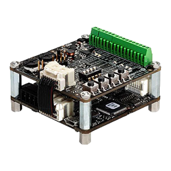
Product Manual Product Description Pluto is a high performance closed loop servo drive controller suitable for DC brushed, steppers, voice coils and brushless motors. Its design includes multiple communication ports, enabling thus a wide choice of interfacing methods. Its extended voltage operating range allows its use in several applications, and the small footprint and the needless of an external heatsink allow the controller to be a valid OEM for critical-size applications. - Page 9 Product Manual Electrical and power specifications Motion control specifications Supported motor Rotary or linear brushless (trapezoidal and sinusoidal) types DC brush Voice coil 2 phases bipolar stepper 3 phases stepper Power stage PWM 40 kHz (default) frequency 80 kHz (high PWM frequency, configurable Current sensing On phases A, B and C using 3 terminal shunt resistors.
- Page 10 Product Manual Electrical and power specifications Inputs/outputs and protections Inputs and 2 x non isolated single ended digital inputs. GDI1, GDI2 (5 V TTL logic, 24 V outputs tolerant) 2 x non isolated high speed differential digital inputs. HS_GPI1 Pulse, HS_GPI2 Direction (5 V logic, 24 V tolerant) 1 x (±10 V) differential analog input (12 bits).
-
Page 11: Hardware Revisions
Product Manual Electrical and power specifications Environmental and mechanical specifications Variant PLU-1/48 PLU-5/48 PLU-8/48 Ambient air -40 ºC to +50 ºC full current (operating) temperature +50 ºC to +100 ºC current derating (operating) -50 ºC to -40ºC and 100ºC to +125 ºC (non-operating) Maximum 5% - 85% (non-condensing) humidity... -
Page 12: Power And Current Ratings
*Hardware revision is screen printed in white below motor connector, on the bottom of the Pluto. Power and current ratings The Pluto is capable of providing the nominal current from -10ºC to 50ºC ambient air temperature without the need of any additional heatsink or forced cooling system. From 50ºC to 80ºC of ambient temperature a current derating is needed to avoid a system overtemperature. -
Page 13: Power Losses Calculation (Heat Dissipation)
This increases conduction losses on the reverse polarity protection circuitry. Current ratings The Pluto Servo drive has no cold plate, so the board itself is the heatsink. Power losses cause the driver to increase its temperature following the this formula: Since T <... -
Page 14: System Temperature
Dynamic application (non-constant current) The Pluto has a big thermal inertia that allows storing heat during short current pulses (exceeding nominal current) without causing an over temperature. This allows achieving high peak current ratings without need of additional heatsink. -
Page 15: Pluto Architecture
Dynamic model For systems with a time > than 3 τ the dynamic model should be used. Instead of considering thermal resistances you should consider the thermal impedance. The Pluto model can be simplified as a 2nd order. Pluto architecture... - Page 16 Product Manual Connectors Next figures show PlutoServo Drive connectors position, functionalities and pinout. For EtherCAT connectors pinout see below 16/88...
-
Page 17: Can Interface Connector
Product Manual CAN interface connector The CAN interface connector is a 3 pin pluggable terminal block with 3.5 mm pitch. Pin numbers and connectors pinout are shown below: Name Description CAN ground CANL CAN bus line dominant low 17/88... -
Page 18: Feedbacks Connector
This connector has changed from previous hardware revisions. Please see Hardware revisions for more information. Feedbacks connector Pluto has a 12 pin TE Micro-Match connector for motor feedbacks. Part number TE 1-338068-2 Polarization hole on PCB indicates pin 1 and ensures correct cable position. See Feedback connections more information about different feedbacks wiring. -
Page 19: I/O Connector
Hardware revisions for more information. For Sin-Cos encoder see the Nix Servo Drive I/O connector Pluto has a 16 pin TE Micro-Match connector for inputs and outputs. Part number 1-338068-6 . See Potentiometer PWM encoder interface for wiring information. Polarization hole on PCB indicates pin 1 and ensures correct cable position. -
Page 20: Supply And Shunt Connector
LS_GPI1 Low speed digital single ended input 1 +5V_EXT +5V 200mA max output (shared with feedback connector) Note: In previous Pluto versions (1.0.1R) which had CLIK-Mate connectors this pin was connected to GND. Please see Hardware revisions for more information. -
Page 21: Motor Connector
Motor phase C connection Motor protective earth connection, internally connected to supply PE and standoffs USB connector Pluto includes a 5 pin micro-USB connector for USB interface. This allows easy access to the driver configuration using MotionLab Documentation Home or downloading firmware upgrades . -
Page 22: Mating Connectors
20020004- 1788432 20020004-C031B01LF- 649-220004- C031B01LF C031B01LF Feedbacks mating connectors For ribbon cable The easiest and lowest cost option is using a flat ribbon cable with 1.27 mm pitch. Please see Pluto feedbacks cable Manufacturer Manufacturer ID Farnell Digikey Mouser... -
Page 23: I/O Mating Connectors
Multi-core crimped cable Some applications require single cables with crimp terminals. This makes the wiring cleaner and is a preferred option for volume applications. Pluto connectors include locking latches that provide audible click during mating and ensure assembly robustness. ... -
Page 24: Motor Mating Connector
Multi-core crimped cable Some applications require single cables with crimp terminals. This makes the wiring cleaner and is a preferred option for volume applications. Pluto connectors include locking latches that provide audible click during mating and ensure assembly robustness. ... -
Page 25: Usb Mating Connector
Recommended wire section is 0.5 mm² ~ 1.5 mm². USB mating connector USB 2.0 A to micro-B (as used in mobile phones chargers) are valid for interfacing the Pluto. Following are suggested part numbers. Shorter USB cables are preferred whenever possible... -
Page 26: Ethercat Input And Output Connector
Product Manual EtherCAT input and output connector Pluto EtherCAT variant includes 2 RJ45 ports for the EtherCAT communication, the input connector (PORT 1) and the output connector (PORT 2). The pinout is shown below. 26/88... -
Page 27: Wiring And Connections
Product Manual EtherCAT input (PORT 1) Name Description TX_D+ Transmit Data+ line TX_D- Transmit Data- line RX_D+ Receive Data+ line +2V5 2.5 V generated internally +2V5 2.5 V generated internally RX_D- Receive Data- line Not connected GND_CHASSIS Connected to the connector chassis EtherCAT output (PORT 2) Name Description... -
Page 28: Power Supply Wiring
Product Manual Wiring and Connections Once the Pluto Servo Drive is mounted, the device can be wired. Proper wiring, grounding and shielding are essential for ensuring safe, immune and optimal servo performance of the drive. Next pages show detailed connection recommendation as well as technical details of each interface. -
Page 29: Recommended Power Supply Connection
Pluto-8/48, 1000 Recommended power supply connection The recommended power supply connection is shown below. Twisted power supply cables are preferred to reduce electromagnetic emissions and increase immunity. Distance between line filter and Pluto Servo Drive should always be minimized. 29/88... -
Page 30: Simplified Battery Supply Connection
For safety reasons, the power supply must always provide full galvanic isolation. Simplified battery supply connection Next figure shows a simplified wiring diagram for the Pluto Servo Drive power supply from a battery. Connection of multiple drivers Always use "star" connections when different servo drives are connected to the same power supply. -
Page 31: Power Supply Wiring Recommendations
Always use good quality plated screws that won’t oxidize or lose conductivity during the expected lifetime. Whenever possible, mount the Pluto Servo Drive on a metallic conductive surface connected to earth. Note that the PE terminal is internally connected with the Pluto Servo Drive standoffs. Wire section The minimum wire section is determined by the current consumption and the allowed voltage drop across the conductor. -
Page 32: Motor Output Wiring
0.5 mm (20 AWG) Wire length The distance between the Pluto Servo Drive and the power supply should be minimized when possible. Short power cables are preferred. For best immunity use twisted and shielded 2-wire cables for the DC power supply. This becomes crucial in long cable applications. -
Page 33: Dc Motors And Voice Coils Actuators
Stepper motors The Pluto Servo Drive is capable of controlling 4 wire bipolar stepper motors. The connection diagram is shown in next figure. Note that stepper phases A- and B- are connected together to Pluto PH_C output of Motor connector . -
Page 34: External Shunt Resistor
While decelerating a motor (abrupt motion brakes or reversals), the mechanical energy is converted into electrical energy by the motor. This energy is regenerated into the power supply and could lead to an increase of the supply voltage. To absorb this energy the Pluto incorporates a shunt transistor to connect an external braking resistor. - Page 35 Turn on voltage for shunt circuit, user configured maximum Bus voltage [V] Hysteresis point of Bus voltage during deceleration cycles [V] Bus capacitance [F] >112 µF (Pluto Internal) User configured shunt PWM Duty Cycle Phase current during deceleration [A Motor phase resistance line to line [Ω] Mechanical parameters ω...
- Page 36 If the calculated net deceleration energy (E ) exceeds the energy that bus capacitors can store a shunt resistor is required, see eqn.4. Note that the minimum capacitance is the Pluto internal (600 µF); however typical power supplies have large output capacitances that are parallel to the bus capacitance. Since battery operated systems allow regenerative breaking this equation is not valid in this case.
-
Page 37: Motor Wiring Recommendations
Solid wire 0.5 mm 1.5 mm Wire length The distance between the Pluto Servo Drive and the motor should be minimized when possible . Short cables are preferred since they reduce power losses as well as electromagnetic emissions and immunity. - Page 38 The parasitic capacitance between motor wires should not exceed 10 nF. If very long cables (> 100 meters) are used, this condition may not be met. In this case, add series inductors between the Pluto outputs and the cable. The inductors must be magnetically shielded, and must be rated for the motor surge current.
-
Page 39: Feedback Connections
Hall-effect devices. Pluto Servo Drive also provides a 5 V @ 200 mA output for feedbacks supply. This output is overload and short circuit protected. Additional feedback connections can be found on I/O connector... - Page 40 The Pluto Servo Drive has one differential quadrature encoder interface, with optional index signal input. Index is a single pulse per revolution signal that can be used to know absolute positions. Next table illustrates digital encoder inputs main features.
- Page 41 10 MHz. When single ended encoder is connected, only high signals (ENC_A+, ENC_B+ and ENC_Z+) must be used. Next figures illustrate how to connect a differential and a single ended encoder to the Pluto Servo Drive. Refer to Feedback wiring recommendations for more information about connections and wires.
- Page 42 Product Manual Next figure shows the circuit model of the digital encoder inputs. Encoder broken wire detection For differential digital encoders only a broken wire detection circuit is included. The circuit is based on 3 EX-OR gates only works for differential encoders 42/88...
-
Page 43: Digital Halls Interface
Digital halls can be used for commutation, position and velocity control. Resolution using these sensors is much lower than using encoders. Pluto can use single ended Hall sensors to drive the motor with trapezoidal commutation, but not with sinusoidal commutation. - Page 44 The 1 kΩ pull-up resistors are disconnected when Analog-halls input is selected to prevent the analog data corruption. Next figure shows the circuit model of the digital Halls inputs. Next figure illustrates how to connect the digital halls to the Pluto Servo Drive. Refer to Feedback wiring recommendations for more information about connections and wires.
-
Page 45: Analog Halls Interface
Signals provided by these sensors are typically 5 V peak-to-peak sinusoidal signals, with 2.5 V offset and a phase shift of 120 degrees. These sensors can be used for a fine positioning of the rotor. Pluto analog halls inputs main features are shown in next table:... -
Page 46: Analog Input Feedback - Potentiometer
Analog input feedback - Potentiometer The Pluto can use an analog signal as position and velocity feedback element. In this case, rotor position or velocity is calculated depending on the voltage level of one analog input. There are 2 analog inputs with different input voltage range. - Page 47 Product Manual Specification Value Number of inputs Type of input (input 2) Differential ESD protected Type of input (input 1) Single ended ESD protected ESD capability (input 2) IEC 61000-4-2 (ESD) ± 15 kV (air), ± 8 kV (contact) ESD capability (input 1) IEC 61000-4-2 (ESD) ±...
- Page 48 Product Manual Next figure shows the circuit model for the analog input 1: Next figures illustrate how to connect an analog source to the Pluto Servo Drive analog input 2 (for differential and single ended sources). Refer to Feedback wiring recommendations for more information about connections and wires.
-
Page 49: Pwm Encoder Interface
Product Manual Next figure illustrates how to connect an analog single ended source to the Pluto Servo Drive analog input 1. Refer to Feedback wiring recommendations for more information about connections and wires. The following picture shows how to connect a potentiometer as a position sensor using analog input 1: Analog feedback wiring should be physically isolated from motor, AC power and all other power wiring. - Page 50 Product Manual For this feedback interface the high speed digital input 1 is used (HS_GPI1). Next table summarizes main features of this input: Specification Value Number of inputs Type of input ESD protected. Differential ESD capability IEC 61000-4-2 (ESD) ± 12 kV (air), ± 6 kV (contact) Input impedance >...
- Page 51 Product Manual Next figure illustrates how to connect a PWM encoder to the Pluto Servo Drive: Single ended PWM encoders can also be connected to Pluto Servo Drive. Next figure shows how to do it: Refer to Feedback wiring recommendations for more information about connections and wires.
-
Page 52: Dc Tachometer
DC tachometer The Pluto Servo Drive can use a DC tachometer signal as velocity feedback element. Tachometer provides an analog signal whose voltage level is proportional to the rotor speed. There are two analog inputs with different input voltage range. Any of them can be used as velocity feedback input, and can be selected via software depending on the voltage range of the feedback element and its kind of output (single ended or differential). -
Page 53: Io Connections
Any induced disturbance in the wire will have the same magnitude and result in error cancellation. Connect the common of the signal source to Pluto GND if available to minimize common mode noise. -
Page 54: Low Speed (Ls) Single Ended Digital Inputs Interface
Product Manual 1 x 0 ~ 5 V single ended 12 bits analog input Low speed (LS) single ended digital inputs interface The low-speed (LS) non-isolated digital inputs are ready for 5 V levels and are 24 V tolerant. Next table show their electrical specifications. - Page 55 Product Manual Pluto Inputs and outputs are not isolated. The ground of the Pluto Servo Drive and the ground of the devices connected to I/Os must be the same. Otherwise inputs or outputs may be damaged. Three-wire sensors can also be connected to Pluto Servo Drive LS inputs. Next figures illustrate how to do it for PNP and NPN 3 wire sensors (LS_GPI1 can also be used).
-
Page 56: High Speed (Hs) Digital Inputs Interface
Product Manual Pull up resistor value must be chosen in order to ensure ≥ 4 V at the GPI pin considering the input 30 kΩ resistance. For Vcc 5 V, 1 kΩ is recommended. For 24 V 10 kΩ. High speed (HS) digital inputs interface The high-speed (HS) non-isolated digital inputs are ready for 5 V levels and tolerant to 24 V. - Page 57 HS_GPI1+ and HS_GPI2+ inputs are in LOW state by defect. Pluto Inputs and outputs are not isolated. The ground of the Pluto Servo Drive and the ground of the devices connected to I/Os must be the same. Otherwise inputs or outputs may be damaged.
- Page 58 Product Manual If a single ended input is used follow the next recommendation: For three wire sensor connection to these inputs, refer to next figures (HS_GPI2 can also be used). 58/88...
-
Page 59: Analog Inputs Interface
Product Manual Analog inputs interface Pluto Servo Drive has two 12-bit analog inputs with different input voltage ranges. Next table shows their main features: Specification Value Number of inputs Type of inputs Differential (input 2) Single ended (input 1) ESD protected. - Page 60 Product Manual To get a 0 ~ 10 V input range in AN_IN1 input, place a 70 kΩ resistor in series with the input. Next figure shows how to interface voltage sources to the differential analog input 2. The differential analog input is typically used as a command source.
-
Page 61: Digital Outputs Interface
Product Manual To interface to a single ended (non-differential) voltage source, use analog input 1: Digital outputs interface Pluto Servo Drive has two digital non-isolated outputs. Refer to IO Connector for connector's position and pinout. Next table shows their main features:... - Page 62 Product Manual Specification Value Maximum supply output 30 V (5-24 V typical) Maximum sink/source current Source: low current @ 5 V: 5 mA Sink: 500 mA @ 5 or 24 V ON-OFF delay 124 μs @ 30 V and R = 100 kΩ...
- Page 63 Product Manual 24 V outputs If 24 V outputs are needed, an external power supply should be used. For this option, outputs may be connected as voltage or current outputs. Next figures illustrate how to do it (GPO1 can also be used). 63/88...
- Page 64 Actually, there are other options to avoid inductive kicking. Instead of a diode, a varistor or a RC snubber in parallel with the brake can also be used. This will improve transistor turn off time. Next figure shows how to connect an inductive load to Pluto outputs (GPO1 can also be used). 64/88...
-
Page 65: Torque Off Input
Product Manual Pluto Inputs and outputs are not isolated. The ground of the Pluto and the ground of the devices connected to I/Os must be the same. Otherwise inputs or outputs may be damaged. Torque off input As assembly option (custom), the Pluto Servo Drive has a torque off input used to prevent motor torque in an emergency event while the Pluto remains connected to the power supply. -
Page 66: Command Sources
The torque off input is not a safety critical torque off input (Safe Torque Off). It should not be used for safety critical applications. Command sources The command source input for the Pluto Servo Drive can be provided by one of the following options: Network interface (CANopen or USB). Stand alone. -
Page 67: Network Interface
Pluto Servo Drive is provided with an internal non volatile memory. Through the appropriate software tool, user can save instructions to this 1 Mb (128K x 8bit) EEPROM, allowing Pluto Servo Drive to work in standalone mode. In this mode, there is no need of an external command source. -
Page 68: Step And Direction
General purpose high speed digital inputs are used here. HS_GPI1 is the Step input, and HS_GPI2 is the Direction input. Next figures illustrates how to connect a step and direction command source to the Pluto Servo Drive (for differential and single ended mode). -
Page 69: Pwm Command
Product Manual Refer to Connectors position and pinout for information about connector position and pinout, and see High-speed (HS) digital inputs interface for more information about digital inputs. Next figure shows how to connect this input: PWM command PWM input signal specification For this feedback interface the High Speed digital input 2 is used (HS_GPI2). - Page 70 Product Manual Specification Value ESD protected. Differential using RS422 receiver. ESD capability IEC 61000-4-2 (ESD) ± 15 kV (air), ± 8 kV (contact) Input current 2 mA @ 5 V; 5 mA @ 15V High level differential input voltage (HS_GPI2+ - HS_GPI2-) > 150 mV Low level differential input voltage (HS_GPI2+ - HS_GPI2-) <...
- Page 71 Product Manual direction. Position and torque modes work in a similar way. This mode uses High speed digital input 2.Refer to Connectors for information about connector´s position and pinout, and see High-speed (HS) digital inputs interface for more information about digital inputs. Next figure shows how to connect this input: Dual input mode For this mode two signals are used.
-
Page 72: Encoder Following Or Electronic Gearing
/slave configuration. The gearing ratio (input counts to output counts ratio) can be configured via software. Encoder Following is only a valid option when the Pluto Servo Drive is operated in position mode. The auxiliary encoder signal input should be connected to high speed digital input pins. Master encoder... -
Page 73: Communications
High-speed (HS) digital inputs interface Communications The Pluto Servo Drive provides different network communication interfaces for configuration and operation. All the interfaces can be used to connect any of the supplied software applications or a custom application built with the supplied libraries for the controller. -
Page 74: Can Interface
Product Manual CAN interface Pluto Servo drive supports CAN-Bus (Controller Area Network-Bus), a serial communication protocol developed by Bosch for exchanging information between electronic control units on automobiles. Next table shows CAN interface pins specifications: Specification Details Baud rate from 125 kbps to 1 Mbps (default value) - Page 75 Product Manual Bus termination resistors (120 Ω between CANL and CANH at both ends of the bus) is essential for correct operation of the CAN bus (mainly for long distances and high baud rates). GND and SHIELD The GND line in CANopen devices basically equals potentials between the master and the slaves but is not used for data transmission as the line is fully differential.
-
Page 76: Usb Interface
Use shielded cable with the shield connected to PC end. Shield of micro USB connector is not connected on Pluto. Do not rely on an earthed PC to provide the Pluto Servo Drive earth connection. The drive must be earthed through a separate circuit. - Page 77 Product Manual EtherCAT specific features Ports available LED Signals Status LED Link/Act LED Supported Mailbox SDO info Not supported Segmented SDO Supported SDO complete access Not supported Modes of operation DS402 drive device profile Open loop (vector & scala Velocity Mode Profile torque Profile velocity Profile position...
-
Page 78: Signalling Leds
Product Manual Signalling LEDs 78/88... -
Page 79: Power And Motor Signalling Leds
Product Manual Signalling LEDs Pluto Servo Drive has 5 signalling LEDs near the CAN interface connector and USB connector. Power and motor signalling LEDs Next table shows the meaning of each motor and power LED. Colour Meaning POWER Green LED is on when internal power supply is working. -
Page 80: Ethercat Signalling Leds
Product Manual ERROR State * Description No error Device is in working condition Single Warning At least one of the error counters of the CAN controller has reached or flash limit exceeded the warning level (too many error frames) reached Double Error control A guard event (NMT-slave or NMTmaster) or a heartbeat event (heartbeat... -
Page 81: Ethercat Status Led
Product Manual EtherCAT signalling LEDs The EtherCAT variant of the Pluto has 3 LEDs to indicate the board status. EtherCAT status LED The EtherCAT Plug-in Board has a bicolor GREEN LED. The Green LED is the RUN LED , and the Red... -
Page 82: Software
Product Manual LINK LED Slave State Port opened (no activty on port) Software 82/88... -
Page 83: Installing Motionlab Configuration Software
Once the power supply is on, the POWER LED will switch on. If the POWER LED is not on, please check the wiring. After a few seconds the CAN LED will start blinking. Connect the USB cable to your PC and wait for Windows to recognize the Ingenia USB driver. 83/88... -
Page 84: Updating Your Drive Firmware
Product Manual Open MotionLab from the Programs menu. Once MotionLab has loaded it will automatically detect the connected drives. If no drives are visible click on Scan Again or check you drive wiring. Updating your drive Firmware Before configuring your drive for a new application make sure you have upgraded your drive to the latest firmware revision. -
Page 85: Configuring Your Drive
Product Manual Once MotionLab detects your drive click on Update FW Browse and select the Firmware and click on Update Firmware Click OK to proceed. When updating the firmware all configurations will be lost. If you have already configured your drive make sure to save the configuration before updating the drive. If this method fails please contact support. -
Page 86: Standard Version
Standard version Pluto has a 60 mm x 60 mm footprint and a maximum 15 mm height. The driver is provided with 4 x Ø 3.2 mm holes for M3 standoff mounting. These holes are plated and connected to protective earth (PE). -
Page 87: Disclaimers And Limitations Of Liability
Product Manual Disclaimers and limitations of liability 87/88... - Page 88 INGENIA-CAT rejects all liability for errors or omissions in the information or the product or in other documents mentioned in this document.
Need help?
Do you have a question about the Pluto and is the answer not in the manual?
Questions and answers