
Related Manuals for INGENIA Everest CORE


Summary of Contents for INGENIA Everest CORE
- Page 1 Everest CORE - Product Manual Edition 08/01/2019 For the most up to date information visit the online manual. INGENIA-CAT S.L. AVILA 124 08018 BARCELONA...
-
Page 2: Table Of Contents
P4 Everest CORE Interface connector ....................... 16 Dimensions Application Guide 7.1. Scope and Architecture ............................. 22 7.1.1. Parts of an Everest CORE integration solution....................22 7.1.2. Single-Axis or Multi-Axis approach........................22 7.2. Schematic Design............................... 22 7.2.1. Input Supplies ..............................23 DC Power Supply.............................. - Page 3 Bill of materials ..............................50 7.3. Layout Design..............................50 7.3.1. Required files..............................51 7.3.2. The Everest CORE component .......................... 52 Mechanical layer 5: positioning guide ......................52 Mechanical layer 15: clearances........................53 7.3.3. Layout considerations ............................54 Proposed Layer Stack ............................56 Proposed Design Rules ...
-
Page 4: General Information
The information contained within this document contains proprietary information belonging to INGENIA-CAT S.L. Such information is supplied solely for the purpose of assisting users of the product in its installation. INGENIA-CAT S.L. rejects all liability for errors or omissions in the information or the product or in other documents mentioned in this document. ... -
Page 5: Safety Information
CORE Servo Drive. To ensure maximum safety in operating the Everest CORE Servo Drive, it is essential to follow the procedures included in this guide. This information is provided to protect users and their working area when using the Everest CORE Servo Drive, as well as other hardware that may be connected to it. -
Page 6: Product Description
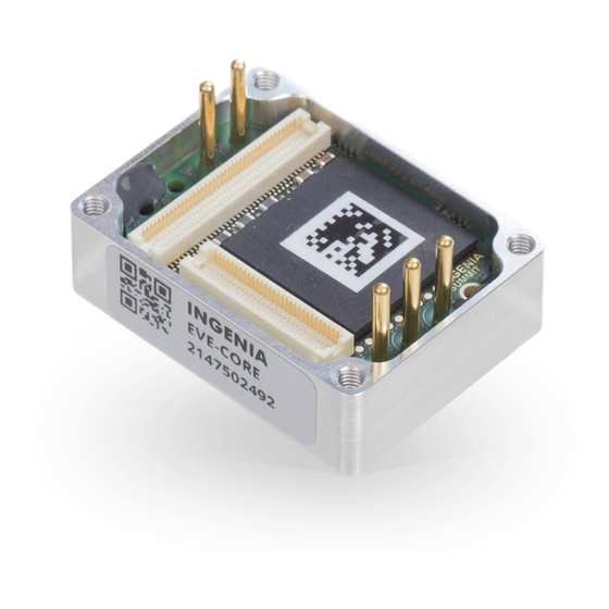
Everest CORE - Product Manual | Product Description 4. Product Description Everest CORE is a high power, highly-integrated, digital servo drive intended to be plugged or soldered to an application-specific daughter board. The drive features best-in-class energy efficiency thanks to its state of the art power stage, and can be easily configured with Ingenia's free-to-download software MotionLab 3. -
Page 7: Specifications
Everest CORE - Product Manual | Product Description 4.2. Specifications Part number → EVE-CORE Electrical and power specifications Minimum DC bus supply voltage Maximum DC bus supply voltage 80 V (continuous) 85 V (peak 100 ms) Recommended power supply 12 V ~ 72 V... - Page 8 • Absolute Encoder: up to 2 at the same time, combining any of the following: • BiSS-C (up to 2 in daisy chain topology) • SSI *Only a specific subset of absolute encoders are supported. Contact Ingenia for further information. Supported target sources Network communication (Motion Control Bus) Control modes •...
- Page 9 Everest CORE - Product Manual | Product Description Motor brake output Dedicated, PWM capable, 3.3 V digital output for driving a mechanical brake. Turn-on and turn-off times are configurable. Enabling this function would require an external transistor or power driver. Safe Torque OFF inputs 2 x dedicated, non-isolated STO digital inputs (3.3 V and 5 V tolerant).
-
Page 10: Thermal Specifications
The following figure show the maximum phase current at different case temperatures and DC bus voltages. Here current is expressed in RMS. To obtain the equivalent current in amplitude just multiply it by √2 . To ensure a proper performance of Everest CORE, the case temperature must be held always below 85 ºC (T = 85 ºC). - Page 11 Everest CORE - Product Manual | Product Description Following figure show the theoretical power losses at different operating points. Take a look to the Thermal Dissipation section below to learn how to dimension a heatsink to allow Everest CORE reaching a target current under an specific ambient temperature. INGENIA | 08/01/2019...
-
Page 12: Pinout
Everest CORE - Product Manual | Pinout 5. Pinout 5.1. Connectors Overview 5.2. P1 and P2 Power pins P1 Supply Power pins Name Type Function POW_SUP Power Power supply positive (DC bus). GND_P Power supply negative (Power Ground). Chassis Protective Earth connected to driver housing and fixing M2.5 threads. -
Page 13: P3 Feedback Connector
Direct solder to PCB. TH pad with min. hole Ø 1.63 mm. Ensure PCB track are wide enough to withstand the target current. 5.3. P3 Feedback connector The pinout of the Feedback connector is exactly the same for for Everest CORE (EVE_CORE) and Everest NET (EVE_NET) although the position of the connector is different. - Page 14 Everest CORE - Product Manual | Pinout P3 Feedback connector Signal Description Type Signal Description Type name name GND_A Analog Ground. Do not connect Power GND_A Analog Ground. Do not connect Power to GND_D directly, use a ferrite to GND_D directly, use a ferrite bead or 1 Ω...
- Page 15 Everest CORE - Product Manual | Pinout 27 CLL Reserved. Must be tied or 28 DIG_E Digital encoder 1 Index. pulled-down to GND_D. NC_1Z 29 CHL Reserved. Must be tied or 30 DIG_E Digital encoder 2 A. pulled-up to 3.3 V. NC_2A 31 DNC Reserved.
-
Page 16: P4 Everest Core Interface Connector
0.5 mm pitch. Center strip, gold- plated surface mount contacts. 3 mm stacking height. DF12(3.0)-60DP-0.5V(86 DF12(3.0)-60DS-0.5V(86) 5.4. P4 Everest CORE Interface connector Although using the same physical connector as Everest NET (EVE-NET), position and pinout is different in Everest CORE (EVE-CORE). - Page 17 Everest CORE - Product Manual | Pinout 5V_D 5 V, 300 mA continuous logic Power 5V_D 5 V, 300 mA continuous logic Power supply input. Must be low input supply input. Must be low input 5V_D 5V_D ripple and ensure ±2% ripple and ensure ±2% regulation tolerance or less.
- Page 18 Everest CORE - Product Manual | Pinout 33 \STO1 Safe Torque Off input 1 (non- Input 34 \STO2 Safe Torque Off input 2 (non- Input isolated). Both \STO1 and isolated). Both \STO1 and \STO2 must be high-level (3.3 V \STO2 must be high-level (3.3 V...
- Page 19 • "DNC" means Do Not Connect. Pins marked with DNC must not be tied to any driving voltage, including GND or 3.3 V. Motion Control Bus Everest CORE can be controlled as a slave by means of its proprietary Motion Control Bus (MCB). Check how in the Summit Series Reference Manual.
- Page 20 Everest CORE - Product Manual | Pinout Manufacturer Everest CORE Required mating Description connector connector Hirose Electric 80-pin mezzanine stacking board connector. 0.5 mm pitch. Center strip, gold- plated surface mount contacts. 3 mm stacking height. DF12(3.0)-80DP-0.5V(86 DF12(3.0)-80DS-0.5V(86) INGENIA | 08/01/2019...
-
Page 21: Dimensions
Everest CORE - Product Manual | Dimensions 6. Dimensions All dimensions are in mm. All tolerances ≤ ±0.2 mm 3D Model For further detail, download the STEP model. INGENIA | 08/01/2019... -
Page 22: Application Guide
7.1.2. Single-Axis or Multi-Axis approach The simplest way to integrate Everest CORE is to develop an interface board to hold 1 drive module and a Master device. This way, the Master can command the Everest CORE as a slave, and the Everest CORE will control the motor accordingly. ... -
Page 23: Input Supplies
Although typically not part of an interface board, but wired outside, this could be one of the main and first elements to take care of, as the way it is dimensioned could affect the rest of the design. Everest CORE generates 3-phase currents by means of an inverter topology power stage, so it require a DC power supply to feed its internal DC bus. -
Page 24: Dc Bus Input Stage
Everest CORE is a switched power regulator using a very fast state-of-the art switching technology. This allows Everest CORE to be extremely efficient, but at the cost of requiring a relatively more sophisticated input stage to avoid transmitting a "sharp" ripple voltage through the power supply lines. This is of an special importance when sharing the DC bus with other sub-systems or when targeting EMC-related certifications, as CE marking. - Page 25 Finally, it is advisable to include sourge and ESD protection in the power DC input to reinforce the immunity ratings of the Everest CORE. A TVS could do the job for ESD protection, but might be insufficient in front of a sourge, where suppression of large but very short power peaks is not as relevant as the response in front of a wide and long INGENIA | 08/01/2019...
- Page 26 POW_SUP_IN- Negative or reference voltage terminal of the power supply input POW_SUP Internal DC bus positive supply. Could be connected to Everest CORE power pin 1 of P1 if no Inverted Polarity protection is implemented Protective Earth. To be connected to chassis of Everest CORE. Could be left unconnected in specific cases INGENIA | 08/01/2019...
-
Page 27: Logic Supply
Signal Description GND_P Internal DC bus reference voltage. To be connected to power pin 2 of P1 in Everest CORE Design Notes • POW_SUP net would be connected to POW_SUP_S1 or POW_SUP_S2 depending on the line filter implemented. If no line filter is on-board, it would be connected to POW_SUP_IN+. - Page 28 Output current required The minimum output current specified above is only for Everest CORE, so does not include the Interface Board self-consumption or its capability to deliver current to other external circuits. A couple o valid DC/DC examples:...
- Page 29 Everest CORE - Product Manual | Application Guide Second, 5 V is converted to 3.3 V by means of a simple LDO. The Everest CORE does not consume any current from this 3.3 V, so it must be enough to cover the self-consumption of the Interface Board plus the amount of current to be sent to external circuits (see 3.3 V and 5 V Output Supplies chapter below).
-
Page 30: Protective Circuits
Inverse Polarity Protection This circuit is intended to block any current going into Everest CORE when the power supply is connected in inverted polarity. If this circuit is not present, it is suggested to select a polarised power supply connector. ... -
Page 31: Shunt Braking Resistor Transistor
• Not doing anything: re-injection could not be an issue, specially when the nominal voltage of the motor is way smaller than the one of the drive (i.e. driving a 24 V motor with Everest CORE). If the re-injection is not too strong, the internal DC bus of the drive will increase, but not enough to reach dangerous levels, so the drive will simply withstand it. ... - Page 32 To be connected to the negative terminal of the power resistor GND_P Power supply reference voltage. To be connected to power pin 2 of P1 in Everest CORE GND_D Logic supply reference voltage. To be connected to pins 39, 59 or 60 of Everest CORE Interface connector INGENIA | 08/01/2019...
-
Page 33: Safe Torque Off (Sto)
Everest CORE - Product Manual | Application Guide Design Notes • OVERVOLTAGE net must be tied to any of the GPOx pins of Everest CORE Interface connector (pins 55, 56, 57 or 43). Then, the Everest CORE must be configured to map the Overvoltage signalling functionality to this specific GPO, which will then stop working as a general purpose digital output. - Page 34 To be connected to pin 34 of Everest CORE Interface connector GND_D Logic supply reference voltage. To be connected to pin 32 of Everest CORE Interface connector Design Notes • STO_RET is tied together from the 2 circuits, but could be wired separately.
-
Page 35: Inputs And Outputs
Schematic A resistor limits the current while a Zener diode saturates the voltage. Everest CORE will detect as "low" any voltage lower than 0.8, and as "high" any voltage greater than 3 V, while still being tolerant to input voltages up to 30 V. - Page 36 To be connected to pin 58 of Everest CORE Interface connector GND_D Logic supply reference voltage. To be connected to pins 59 and 60 of Everest CORE Interface connector Design Notes • For simplicity, the proposed solution is not opto-isolated. Therefore, the input signals generator (could be a PLC or other controller) must share the Ground with Everest CORE.
-
Page 37: Digital Outputs
Digital Outputs This simple circuit can be used to convert the 3.3 V push-pull digital outputs of Everest CORE into 5 V open collector with weak pull-ups. This will invert the logic polarity of the output, but at the same time it will provide the capability of driving greater loads. -
Page 38: Mechanical Brake Output
• When using the load in push-pull configuration, the 1 kΩ resistor set the output impedance and limit the current. In this case, note that the polarity of the GPOx signal coming from Everest CORE will be inverted in the output. - Page 39 In case of a low voltage DC bus Everest CORE DC bus can be driven from a very low voltage power supply, but still a 24 V brake might be required. In the event that the DC bus is lower than the brake driving voltage, the signal BRAKE+ must not be tied to the DC bus (either SUP_PROTECTED, POW_SUP or power pin 1 of P1 in Everest CORE).
-
Page 40: Output Supplies
Everest CORE - Product Manual | Application Guide Bill of materials Designator Part Number Manufacturer Package Value / Description SK310A-LTP Micro Commercial SMA / DO-214AC Diode Schottky, 3 A, 100 V SSM3K324R,LF Toshiba SOT-23-3N Logic-level N-Channel MOSFET, 30 V, 4 A RMCF0402FT100... - Page 41 +3.3 V output supply for external circuits GND_D To be connected to GND_D in the Everest CORE Interface connector Design Notes • R1 and R2 set the current limit. Considering the tolerances of both the load switch and the resistor, the current would be limited to a minimum of 246 mA and a maximum of 315 mA, with a typical value of 282 mA.
-
Page 42: Communications
Motion Control Bus Everest CORE is interfaced by means of the proprietary Motion Control Bus protocol. The physical layer required is similar to SPI, working under 3.3 V levels, and requiring almost nothing other than PCB traces from the on-board Master device to the Everest CORE. -
Page 43: Digital Halls
MCB_SYNC1 Synchronisation signal 1. To be connected to pin 24 of Everest CORE Interface connector MCB_IRQ Everest CORE Interrupt Request output to Master. To be connected to pin 26 of Everest CORE Interface connector \HW_RESET Everest CORE Reset input. To be connected to pin 38 of Everest CORE Interface connector GND_D Logic supply reference voltage. To be connected to pins from 13, 15, 17, 19, 21, 23 and 25 of... - Page 44 HALL_IN_1 Digital hall inputs from motor HALL_IN_2 HALL_IN_3 HALL_1 To be connected to pins 17, 19 and 21 of Everest CORE Feedback connector HALL_1 HALL_1 GND_D Logic supply reference voltage. To be connected to pin 15 of Everest CORE Feedback connector Design Notes •...
-
Page 45: Quadrature / Incremental Encoder
Everest CORE - Product Manual | Application Guide • The RC filter makes a 1st order f (-3dB) ≈ 16 kHz, but having the bandwidth of U1, the circuit should work fine with signals up to 5 kHz. • C5 is decoupling capacitor for U1. - Page 46 +5V_D +5 V Logic supply DIG_ENC_A To be connected to pins 24, 26 and 28 of Everest CORE Feedback connector to feed Digital Encoder 1 DIG_ENC_B To be connected to pins 30, 32 and 34 of Everest CORE Feedback connector to feed Digital...
-
Page 47: Absolute Encoder
It sets 2 half-duplex channels, one for the "clock" signal, which is always a transmitter driven from the Everest CORE, and the other for the "data" signal, which is always a receiver. With this, Everest CORE will be able to interface most SSI or BISS-C absolute encoders available. - Page 48 ABSENC_DATA_N Data input differential pair to absolute encoder ABSENC_DATA_P ABSENC_CLK Clock signal from Everest CORE to be connected to pin 38 of Feedback connector or pin 50 of Interface connector ABSENC_DATA Data signal from Everest CORE to be connected to pin 40 of Feedback connector or pin 51 of...
-
Page 49: Led Signalling
8-VSSOP RS485/422 half-duplex transceiver, 20 Instruments Mbps 7.2.6. LED Signalling Everest CORE allows directly driving small LEDs for signalling up to 3 mA. This circuits would provide signalling for Logic supply and Fault state of the Everest CORE. INGENIA | 08/01/2019... -
Page 50: Schematic
TLMG1100-GS08 Vishay 0603 Green diode LED, 35 mcd, 100 ºC 7.3. Layout Design This part of the guide is intended to provide the necessary indications to design a PCB in which the Everest CORE can be properly integrated. INGENIA | 08/01/2019... -
Page 51: Required Files
PCB, or be plugged into a receptacle mating contact. The first approach would allow Everest CORE to reach its specified nominal phase current, but it will not be possible to unplug it from the interface board. On the other hand, the second approach will be limited to the rated current of the contacts, but allowing the Everest CORE to be unplugged if required. -
Page 52: The Everest Core Component
7.3.2. The Everest CORE component The Everest CORE is not directly plugged to a PCB, but instead it uses components to be plugged to, either along the direct solder or the pluggable approach. This means that the Everest CORE component does not have any terminals, and the Interface board must be set with the terminals of the required mating components, which are: •... -
Page 53: Mechanical Layer 15: Clearances
Mechanical layer 15: clearances Considerations about clearances and general layout advice can be found in Mechanical layer 15. Understand the lines as the limits for component placement outside or below the Everest CORE, in such way that no component should cross them. -
Page 54: Layout Considerations
Only signal traces are represented, with the purpose of pointing the most appropriate way of leaving the Everest CORE. As a rule of thumb, it is preferred to not direct the tracks towards the inside of the Everest CORE, but outwards. - Page 55 Class 6 PCB manufacturing category. This is a quite average level of sophistication, in terms of PCB manufacturing technology, but is sufficient to interface the Everest CORE, thus entailing a cheaper cost. However, very dense designs might go for a less restrictive PCB Class, specially when most of the signals in the mezzanine connectors are used. ...
-
Page 56: Proposed Layer Stack
Power tracks can go through any layer from Mid 1 to Bottom is fine to exit the Everest CORE, but respecting the intended layer stack usage is advised (see below): GND_P will be better fitted through a layer dedicated to ground planes, as Mid 1, and POW_SUP will be better fitted in a layer dedicated to power supplies, as Mid 3 in this example. -
Page 57: Proposed Design Rules
GND_D. Proposed Design Rules Again, many options are plausible here, but consider this specific set of rules as the minimum required to integrate the Everest CORE without entailing an additional handicap. Rule Value Minimum clearance to Power conductors (external layers) 0.5 mm... -
Page 58: Service
GIZATECH www.gizatech.eu/ comercial@milexia.es ANTRIMON MOTION Switzerland www.antrimon.com motion@antrimon.com Turkey FEMSAN www.femsan.com melike@femsan.com United MOTION CONTROL www.motioncontrolproducts.com info@motioncontrolproducts.com Kingdom PRODUCTS United States NAMPRO www.namproinc.com sales@namproinc.com United States GROUP SIX www.grp6.com ingenia@grp6.com INGENIA-CAT S.L. 8-14 MARIE CURIE, ADVANCED INDUSTRY PARK 08042 BARCELONA...
Need help?
Do you have a question about the Everest CORE and is the answer not in the manual?
Questions and answers