
Related Manuals for INGENIA Everest XCR


Summary of Contents for INGENIA Everest XCR
- Page 1 Everest XCR - Product Manual Edition 08/04/2019 For the most up to date information visit the online manual. INGENIA-CAT S.L. AVILA 124 08018 BARCELONA...
-
Page 2: Table Of Contents
8.3. EtherCAT Status LEDs ............................30 8.4. CANopen Status LEDs ............................30 Wiring and Connections 9.1. Everest XCR Connection Diagram ........................32 9.2. Protective Earth ..............................33 9.3. Power Supply and Motor Power........................35 9.3.1. Single Power Supply ............................35... - Page 3 9.3.2. Dual Power Supply ............................35 9.3.3. Power Supply EMI Filter............................. 36 9.3.4. Shunt Braking Resistor Connection ........................36 9.3.5. Motor Connections............................. 37 3 Phase Brushless .............................. 37 DC Motor ................................37 Motor Choke ............................... 38 9.3.6. Power Wiring Recommendations ........................38 Cable Selection ..............................
-
Page 4: General Information
The information contained within this document contains proprietary information belonging to INGENIA-CAT S.L. Such information is supplied solely for the purpose of assisting users of the product in its installation. INGENIA-CAT S.L. rejects all liability for errors or omissions in the information or the product or in other documents mentioned in this document. ... -
Page 5: Safety Information
XCR Servo Drive. To ensure maximum safety in operating the Everest XCR Servo Drive, it is essential to follow the procedures included in this guide. This information is provided to protect users and their working area when using the Everest XCR Servo Drive, as well as other hardware that may be connected to it. -
Page 6: Product Description
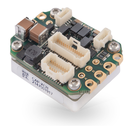
4. Product Description Everest XCR is a high power, highly-integrated, digital ready-to-go servo drive. The drive features best-in-class energy efficiency thanks to its state of the art power stage, and can be easily configured with Ingenia's free-to- download software MotionLab 3. -
Page 7: Specifications
Everest XCR - Product Manual | Product Description 4.2. Specifications Part number → EVE-XCR Electrical and power specifications Minimum power supply voltage Maximum absolute power supply 80 V (continuous) voltage 85 V (peak 100 ms) Recommended power supply 12 V ~ 72 V... - Page 8 Everest XCR - Product Manual | Product Description Current sense resolution Current gain is configurable in 4 ranges: (configurable) • 2.475 mA/count • 1.352 mA/count • 0.570 mA/count • 0.379 mA/count Current sense ranges Current ranges for the 4 configurable current gains: (configurable) •...
- Page 9 Everest XCR - Product Manual | Product Description Inputs/outputs and protections General purpose Inputs and 4 x non-isolated single-ended digital inputs - 5 V logic level & 3.3 V outputs compatible. Can be configured as: • General purpose • Positive or negative homing switch •...
- Page 10 Everest XCR - Product Manual | Product Description Protections • Hardcoded / hardwired Drive protections: • Automatic current derating on voltage, current and temperature • Short-circuit Phase to DC bus • Short-circuit Phase to Phase • Short-circuit Phase to GND • Configurable protections: •...
- Page 11 Everest XCR - Product Manual | Product Description Case temperature Operation: • -40 ºC to +60 ºC at full current (Minimum power up temperature is -30 ºC) • +60 ºC to +85 ºC with derated current For further information, see Thermal Specifications below.
-
Page 12: Product Revisions
Everest XCR - Product Manual | Product Description 4.3. Product Revisions Revision Date Notes 01 Jun 2018 Initial prototype 01 Oct 2018 Second prototype. Known issues or pending features: • Ethernet physical layer is affected by commutation noise 20 Dec 2018 ... - Page 13 Notice that current is expressed in RMS. To obtain the equivalent current in amplitude just multiply it by √2 . To ensure a proper performance of Everest XCR, the case temperature must be held always below 85 ºC (T = 85 ºC) Following figure show the theoretical Power Losses at different operating points.
- Page 14 Everest XCR - Product Manual | Product Description Please, use the following procedure to determine the required heatsink: 1. Based on the voltage & continuous current required by your application and Current derating graph determine the Case temperature T . Remember that Case temperature must be always below 85 ºC (T <...
-
Page 15: Ethercat Specifications
Everest XCR - Product Manual | EtherCAT Specifications 5. EtherCAT Specifications Ports available LED Signals Status LED Link/Act LED Supported Mailbox CoE, FoE, EoE SDO info Supported Segmented SDO Supported SDO complete access Supported Modes of Operation DS402 drive device profile Voltage mode... -
Page 16: Installation
3. Secure the drive in place to prevent any damage. 6.1.1. Back Installation The preferred way to assemble the Everest XCR is from the back using a thermal interface tape (Suggested part numbers are T-Global Technology LI98-1140-27-0.25, for best assembly strength and tolerant to minor surface imperfections, LI98-1100-27-0.15 for high quality flat rectified surfaces or Berquist Bond-Ply 100 series) and 4 x M2.5... -
Page 17: Front Installation
Everest XCR - Product Manual | Installation 6.1.2. Front Installation Front installation can be done using the Flat heatsink that is supplied with the thermal tape and 4 x M2.5 x 8 DIN965 screws (PN EVE-FHS). . 1. Assemble the Everest-XCR to the flat heatsink following the Back Installation process. ... -
Page 18: Rework
Everest XCR - Product Manual | Installation 6.1.3. Rework Rework that requires removing the Everest from the plate should be done carefully: 1. Remove the 4 M2.5 screws. 2. Separe the Everest from the heatsink by prying, torquing or peeling. Make sure the forces are applied to the Everest enclosure and not to the PCB or connectors. ... -
Page 19: Connectors Guide
Everest XCR - Product Manual | Connectors Guide 7. Connectors Guide 7.1. Connector Overview 7.2. Supply P1 connector 2.6 mm diameter gold plated solder pads or flying leads option. Pad pitch is 5.08 mm. Signal Function POW_SUP Power supply positive GND_P Power supply return... -
Page 20: Motor
Everest XCR - Product Manual | Connectors Guide Notes Recommended section wire is 2.5 mm ~ 5.3 mm , AWG 10 ~ AWG 13 for applications working at maximum current. Adapt the cable diameter to your current needs. It is recommended to use flexible silicone cables to ensure low mechanical stress to the board as well as high temperature ratings (≥... - Page 21 Everest XCR - Product Manual | Connectors Guide J1 connector 20 pins 2 row Pico-Clasp 1 mm pitch header. Molex 501190-2027 Signal Function +5V_OUT 5 V 200 mA total max. Pins 1, 9, 14 are internally connected. GND_D Digital signal ground ENC_A+/DATA2+...
- Page 22 Everest XCR - Product Manual | Connectors Guide DATA1- Absolute encoder 1 DATA negative signal input. For single ended absolute encoders with TTL or CMOS levels leave this pin floating and connect the signal to DATA+. CLK1- Absolute encoder 1 CLK negative signal output. For single ended absolute encoders with TTL or CMOS levels leave this pin floating and connect the clock to CLK+.
- Page 23 Everest XCR - Product Manual | Connectors Guide Intentionally not connected. +5V_OUT +5 V output, can be used for STO circuit. CAN_H CAN bus line dominant high RESERVED Reserved CAN_L CAN bus line dominant low RESERVED Reserved GND_D Digital signal ground Digital input 1 (5V levels)
-
Page 24: Ethercat Connectors
Everest XCR - Product Manual | Connectors Guide GND_D Digital signal ground, logic supply negative MOTOR_TEMP_ Motor temperature sensor return (referred to GND_D). Do not use this pin as GND for any other purpose than the negative for motor temperature sensing. Notes When using power supply only (no logic supply) always connect pins 27 (+LOG_SUP) and 29 (GND_D) of ... -
Page 25: Mating Connectors
Everest XCR - Product Manual | Connectors Guide Note Both network connectors have the same pinout, thanks to auto-negotiation there is no need to make crossed- cables. I.e. TX+ of one device can be connected to TX+ of another. Note that port 0 should be used as EtherCAT IN and port 1 as EtherCAT OUT. -
Page 26: Mating Terminals And Cables Common For All Signal Connectors
7.6.1. Mating terminals and cables common for all signal connectors Everest XCR signal connectors are of Molex Pico-Clasp™ family. All share the same crimp terminals and jumper wires. Given the small size of the connectors, crimping must be done with appropriate tools and application guides provided by Molex. - Page 27 Everest XCR - Product Manual | Connectors Guide Crimper tool Description Hand crimper tool 28-32 AWG Part number Molex 63819-1500 J1, J2, J3, J4 Crimped wires 150 mm Description Molex Pico-Clasp™ 28 AWG black jumper lead socket to socket 150 mm lenght. Gold plated.
- Page 28 Everest XCR - Product Manual | Connectors Guide Wiring accessory: wire to wire solder sleeve Description Wire to Wire Solder Sleeve Heat shrinkable. Can be used to reliably connect pre-crimped wires to specific sensor, feedback or other thin wires. Image B-155-9001 INGENIA | 08/04/2019...
-
Page 29: Signalling Leds
Everest XCR - Product Manual | Signalling LEDs 8. Signalling LEDs Everest XCR Drive provides information through 6 signalling LEDs: • EtherCAT 0 link: LED 6 green • EtherCAT 1 link: LED 1 green • Driver Status: LED2 & LED3 (one bi-color). -
Page 30: Driver Status Leds
Everest XCR - Product Manual | Signalling LEDs 8.2. Driver Status LEDs Two LEDs indicate driver status. Note that both LEDs are grouped into a single red/green package. Identified Name Colour Meaning LED2 RESERVED Green Reserved LED3 FAULT LED is on when an error event has occurred and the drive is trapped in the Fault state. - Page 31 Everest XCR - Product Manual | Signalling LEDs LED5 - ERROR Concept Description LED state Single flash Warning limit At least one of the error counters of the CAN controller has reached or reached exceeded the warning level (too many error frames). Double flash...
-
Page 32: Wiring And Connections
Everest XCR - Product Manual | Wiring and Connections 9. Wiring and Connections 9.1. Everest XCR Connection Diagram Detailed wiring diagram for each module: • Protective Earth INGENIA | 08/04/2019... -
Page 33: Protective Earth
Communications 9.2. Protective Earth Connection of Everest XCR Servo Drive and motor housing to Protective Earth (PE) is required for safety and Electromagnetic Compatibility (EMC) reasons. Electrical faults can electrically charge the housing of the motor or cabinet, increasing the risk of electrical shocks. A proper connection to PE derives the charge to Earth, activating the installation safety systems (differential protections) and protecting the users. ... - Page 34 In those cases connecting GND_P to PE can provide an advantage for EMC. • For best EMC performance Everest XCR should be mounted physically close to the actuator or inside the enclosure.
-
Page 35: Power Supply And Motor Power
Everest XCR - Product Manual | Wiring and Connections 9.3. Power Supply and Motor Power 9.3.1. Single Power Supply The Everest XCR can be powered from a single power supply. Dual Power Supply 9.3.2. For systems where it is necessary to keep communications alive, or keeping position information with incremental sensors while power is off, the drive can be powered from a logic supply input on the I/O connector. -
Page 36: Power Supply Emi Filter
9.3.4. Shunt Braking Resistor Connection A shunt braking resistor can be activated from Everest XCR by using an external transistor. Any of the 4 general purpose outputs can be configured to turn-on when the dc bus exceeds a certain threshold: Shunt. ... -
Page 37: Motor Connections
Everest XCR - Product Manual | Wiring and Connections Shunt resistor calculation tool Additional information on shunt braking resistor sizing and a calculation tool can be found here. 9.3.5. Motor Connections 3 Phase Brushless DC Motor INGENIA | 08/04/2019... -
Page 38: Motor Choke
9.3.6. Power Wiring Recommendations Cable Selection Power cables for the Everest XCR must be designed according to the averaged RMS current of the application. Please follow the next recommendations: • The cable insulator must tolerate ≥ 180 ºC. Silicone or Teflon insulation are suggested. PVC cables are not recommended due to their low operation temperature. ... -
Page 39: Soldering Power Pins
In order to ensure redundancy and safety, the Everest XCR includes 2 separate STO inputs that must be activated or deactivated simultaneously (maximum 1.4 s mismatch). A difference of state between STO1 and STO2 inputs will be interpreted as an abnormal situation, after 1.4 s the drive will be latched in fault state. - Page 40 Everest XCR - Product Manual | Wiring and Connections STO firmware notification A STO stop is notified to the motion controller and creates a fault that can be read externally from any communication interface, however STO operation is totally independent and decoupled from control or firmware.
- Page 41 Everest XCR - Product Manual | Wiring and Connections Status STO1 STO2 Drive function status / status / repo abnor level level stage rt bit statu statu fault STO ACTIVE < 1.8 < 1.8 Drive cannot start or provide power to (No torque to the motor.
-
Page 42: Sto Bypass (Needed When No Sto Functionality Is Implemented)
Everest XCR - Product Manual | Wiring and Connections STO1 and STO2 signals should always change at same time with a maximum of 1.4 s mismatch. This is necessary to have 2 channel redundancy and allow diagnostics, as a mismatch will cause a abnormal fault. -
Page 43: Motor Electromagnetic / Electromechanical Brake
Electromechanical brakes are needed in critical applications where the disconnection of the motor or a lack of electric braking could be dangerous or harmful (i.e. falling suspended loads). Everest XCR Servo Drive includes a brake output on the I/O connector J2. The brake output is an N-Channel MOSFET that can be PWM modulated to reduce effective brake voltage and thus power consumption when energized. ... -
Page 44: External Temperature Sensor Wiring
9.4.3. External temperature sensor wiring The Everest XCR motor safety system connector allows the connection of an external temperature sensor based on changes of resistance (PTC thermistor, bimetal, NTC, PT100, silicon temperature sensors) to measure the motor... -
Page 45: Feedbacks
9.5. Feedbacks The Everest XCR can be connected to a maximum of 3 feedback devices at the same time that might be used for commutation and/or velocity/position control purposes. These devices are connected in the J1 connector of the... - Page 46 Open collector Logic output Push-pull output Pull-up resistor value 1 kΩ Next figures show the typical waveforms of the digital Halls signals. Next figure illustrates how to connect the digital Halls to Everest XCR and a simplified input schematic. INGENIA | 08/04/2019...
-
Page 47: Absolute Encoder 1
Fail safe bias resistors ENC_x+ (positive input) 500 Ω to 5 V ENC_x- (negative input) 500 Ω to 2.5 V (equivalent) Next Figure shows how to connect a single SSI or BISS-C absolute encoder to the Everest XCR servo drive. INGENIA | 08/04/2019... -
Page 48: Absolute Encoder 2
Everest XCR - Product Manual | Wiring and Connections For single-ended devices, connect the positive pins of CLK+ and DATA+ and leave the other pins unconnected. For dual daisy-chain BISS-C use the following connection. Dual BISS-C can be used for redundancy or to read position of the rotor before and after a gearbox. -
Page 49: Incremental Encoder
ENC_x+ (positive input) 1 kΩ to 5 V ENC_x- (negative input) 1 kΩ to 2.5 V (equivalent) The next figure shows how to connect a secondary SSI or BISS-C absolute encoder to the Everest XCR servo drive. 9.5.4. Incremental Encoder Everest XCR can use single-ended or differential digital incremental encoder inputs (also known as quadrature incremental encoders) for velocity and/or position control, as well as for commutation purposes. - Page 50 220 Ω (between ENC_x+ and ENC_x-). Fail safe bias resistors ENC_x+ (positive input) 1 kΩ to 5 V ENC_x- (negative input) 1 kΩ to 2.5 V (equivalent) The wiring of a single-ended encoder to the Everest XCR is shown next: INGENIA | 08/04/2019...
-
Page 51: Feedback Wiring Recommendations
Any induced disturbance in the wire will have the same magnitude and result in error cancellation. • Connect the Everest XCR and encoder GND signals even if the encoder supply is not provided by the drive. • Connection between Everest XCR PE and the motor metallic housing is essential to provide a low impedance path and minimize noise coupling to the feedback. -
Page 52: Digital Inputs Interface
Everest XCR - Product Manual | Wiring and Connections 9.6.1. Digital Inputs Interface The non-isolated digital inputs are ready for 5 V or 3.3 V digital levels. The following table shows their electrical specifications. Specification Value Number of inputs 4 (IN1, IN2, IN3, IN4) -
Page 53: Analog Input Interface
Everest XCR - Product Manual | Wiring and Connections The interface for 3 wire NPN and PNP sensors is shown next. 9.6.2. Analog Input Interface The Everest XCR has a high accuracy fully differential 16-bit analog input AN1. See the specifications next: Specification Value... -
Page 54: Digital Outputs Interface
PE as this could actually increase the noise of the signals. 9.6.3. Digital Outputs Interface Everest XCR Servo Drive has 4 non-isolated digital outputs. These outputs can be used to drive optocouplers, LEDs or other digital circuits. Specification... -
Page 55: Communications
Unloaded output high voltage 4.5 ~ 5 V Unloaded output low voltage 0 ~ 0.5 V The wiring of the digital outputs is shown next: 9.7. Communications The Everest XCR provides the following network communication interfaces for configuration and operation. INGENIA | 08/04/2019... -
Page 56: Canopen Interface
EtherCAT. 9.7.1. CANopen interface Everest XCR Servo Drive supports the CANopen interface, a multi-terminal communication protocol based on CAN (Controller Area Network) bus. When the drive is configured with the CANopen interface the J4 connector ETH Port 0 must be used with a standard Ethernet port for configuration and firmware loading. If your computer has no... -
Page 57: Can Wiring Recommendations
Everest XCR - Product Manual | Wiring and Connections CAN wiring recommendations • Build CAN network using cables with 2-pairs of twisted wires (2 wires/pair) as follows: one pair for CAN_H with CAN_L and the other pair for GND. • Cable impedance should have an impedance of 100 to 140 Ω (120 Ω typical) and a capacitance below 30 pF/ meter. -
Page 58: Ethercat Interface
Ethernet over EtherCAT protocol for further information on how to connect Motion Lab 3. The next figure shows how to connect the Everest XCR in an EtherCAT bus. It is recommended to follow the standard IEC 61918-2013 for best practices. INGENIA | 08/04/2019... -
Page 59: Recommended Ethercat Cables And Connectors
Everest XCR - Product Manual | Wiring and Connections Recommended EtherCAT cables and connectors The following table shows the recommended connectors and cable colors for EtherCAT according to IEC 61918 Appendix H. Signal Function Corresponding Pin for M12-4 M8-4 Cable colour Cable colour... -
Page 60: Ethernet Over Ethercat (Eoe) Protocol - Used By Motion Lab 3
EtherCAT packets allowing to establish a communication between standard Ethernet clients and EtherCAT devices over an EtherCAT network in a transparent way. Thanks to this protocol is possible to configure a specific Everest XCR of the network using Motion Lab without requiring to modify the wiring of the installation. ... - Page 61 Everest XCR - Product Manual | Wiring and Connections EoE and TwinCAT You can find more information on how to configure EoE on Beckhoff TwinCAT in the following link: http:// doc.ingeniamc.com/summit/manuals/reference-manual/tricks-and-tips/setting-up-ethernet-over- ethercat-eoe INGENIA | 08/04/2019...
-
Page 62: Dimensions
Everest XCR - Product Manual | Dimensions 10. Dimensions All dimensions are in mm. All tolerances ≤ ±0.2 mm. Assembly instructions are indicated here: Installation. 3D Model For further detail, download the STEP model. http://distext.ingeniamc.com/products/EVE-XCR/steps/ INGENIA | 08/04/2019... -
Page 63: Service
Spain MORDERNA Spain GIZATECH www.gizatech.eu/ comercial@milexia.es ANTRIMON MOTION Switzerland www.antrimon.com motion@antrimon.com www.femsan.com melike@femsan.com Turkey FEMSAN United MOTION CONTROL Kingdom PRODUCTS www.motioncontrolproducts.com info@motioncontrolproducts.com www.namproinc.com sales@namproinc.com United States NAMPRO United States GROUP SIX www.grp6.com ingenia@grp6.com INGENIA-CAT S.L. AVILA 124 08018 BARCELONA...
Need help?
Do you have a question about the Everest XCR and is the answer not in the manual?
Questions and answers