
Related Manuals for INGENIA Everest XCR


Summary of Contents for INGENIA Everest XCR
- Page 1 Everest XCR - Product Manual Edition 10/15/2018 For the most up to date information visit the online manual. INGENIA-CAT S.L. 8-14 MARIE CURIE, ADVANCED INDUSTRY PARK 08042 BARCELONA...
-
Page 2: Table Of Contents
Contact ................................3 Safety Information 3.1. About this manual............................4 3.2. Warnings................................4 3.3. Precautions ..............................4 Product Description 4.1. Everest XCR part numbering .......................... 5 4.2. Specifications..............................6 4.3. Thermal specifications ........................... 9 Connectors Guide 5.1. Supply................................13 5.2. Motor ................................13 5.3. -
Page 3: General Information
The information contained within this document contains proprietary information belonging to INGENIA-CAT S.L.. Such information is supplied solely for the purpose of assisting users of the product in its installation. INGENIA-CAT S.L. rejects all liability for errors or omissions in the information or the product or in other documents mentioned in this document. ... -
Page 4: Safety Information
XCR Servo Drive. To ensure maximum safety in operating the Everest XCR Servo Drive, it is essential to follow the procedures included in this guide. This information is provided to protect users and their working area when using the Everest XCR Servo Drive, as well as other hardware that may be connected to it. -
Page 5: Product Description
4. Product Description PRELIMINARY Everest XCR is a compact, smart digital servo drive. Thanks to its small size and rugged design it can be mounted virtually anywhere: collaborative robot joints, wearable robots, unmanned ground or aerial vehicles as well as inside motors. -
Page 6: Specifications
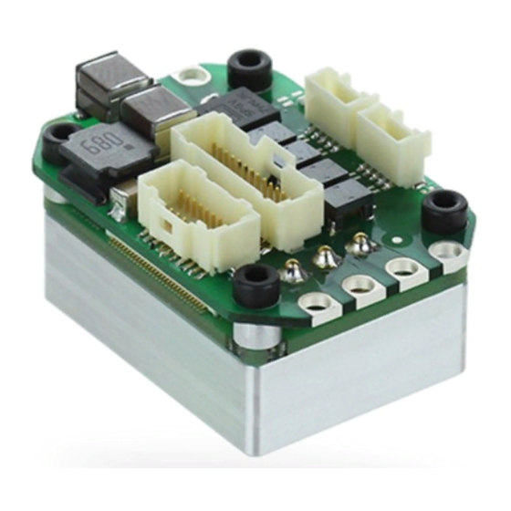
Image Everest XCR EVE-30/100-XCR PRE-PROD 4.2. Specifications A list of features of the Everest XCR Servo Drive is shown next. For further details, please check the Operational characteristics section below. Electrical and power specifications Minimum power supply voltage Maximum absolute power supply... - Page 7 Everest XCR - Product Manual | Product Description Efficiency (at nominal conditions) > 99% Bus voltage utilization > 96% Motion control specifications ≤ 2.5 W Standby power Supported motor types • Rotary brushless (sinusoidal commutation only) Power stage PWM frequency 10 kHz, 20 kHz, 50 kHz & 100 kHz user configurable Current sensing 16 bit ADC resolution.
- Page 8 Everest XCR - Product Manual | Product Description Protections • User configurable: • DC bus over-voltage • DC bus under-voltage • Drive over-temperature • Drive under-temperature • Over-current • Overload (I • Short-circuit protections: • Phase to DC bus • Phase to phase •...
-
Page 9: Thermal Specifications
The following diagram depicts the general dissipation model and the equivalent thermal model. To ensure a proper performance of Everest XCR, the housing temperature must be held below 85 ºC. The following figures show how to calculate the required heatsink The following figure depict the power losses of Everest Core for different phase current values in RMS value. - Page 10 Everest XCR - Product Manual | Product Description Note this is theoretical. The maximum heatsink temperature must be kept at 85ºC. INGENIA | 10/15/2018...
- Page 11 Everest XCR - Product Manual | Product Description For ensuring a good thermal coupling between Everest and the heatsink, a good quality thermal pad is required. For example, a thermal sheet TGX-150-150-0.5-0, which (for Everest XCR contact surface) has an estimated thermal impedance of Rth(c-h) = 0.2 K/W Considering the previous parameters, the maximum thermal impedance heatsink-to-air required can be...
- Page 12 Everest XCR - Product Manual | Product Description INGENIA | 10/15/2018...
-
Page 13: Connectors Guide
Everest XCR - Product Manual | Connectors Guide 5. Connectors Guide 5.1. Supply P1 connector 2.6 mm diameter gold plated solder pads or flying leads option. Pad pitch is 5.08 mm. Signal Function POW_SUP Power supply positive GND_P Power supply return Notes Recommended section wire is 2.5 mm... -
Page 14: Feedback Connector
Everest XCR - Product Manual | Connectors Guide 5.3. Feedback connector J1 connector 20 pins 2 row Pico-Clasp 1 mm pitch header. Molex 501190-2027 Signal Function +5V_OUT 5 V 200 mA total max. Short circuit protected. Pins 1, 9, 14 are internally connected. -
Page 15: Mating Terminals And Cables Common For All Signal Connectors
5.3.1. Mating terminals and cables common for all signal connectors Everest XCR signal connectors are of Molex Pico-Clasp™ family. All share the same crimp terminals and jumper wires. Given the small size of the connectors, crimping must be done with appropriate tools and application guides... - Page 16 Everest XCR - Product Manual | Connectors Guide provided by Molex. Otherwise it is strongly recommended to buy pre-crimped jumper wires and connect to your system using split (or butt) terminals. Spiral wraps are recommended to order and protect the thin wires.
- Page 17 Everest XCR - Product Manual | Connectors Guide Image Part number Molex 079758-1016 Distributor code Digi-Key WM15694-ND J1, J2, J3, J4 Crimped wires 300 mm Molex Pico-Clasp™ 28 AWG black jumper lead socket to socket 300mm lenght Description Image Part number Molex 079758-1017...
-
Page 18: Input / Outputs Connector
Everest XCR - Product Manual | Connectors Guide Wiring accessory: wire to wire solder sleeve Description Wire to Wire Solder Sleeve Heat shrinkable. Can be used to reliably connect pre-crimped wires to specific sensor, feedback or other thin wires. Image B-155-9001 Distributor code Digi-Key A104848-ND 5.4. - Page 19 Everest XCR - Product Manual | Connectors Guide CAN bus line dominant high CAN_H UART_3V3_RX Reserved CAN bus line dominant low CAN_L UART_3V3_TX Reserved GND_D Digital signal ground Digital input 1 (5V levels) Digital input 2 (5V levels) Digital input 3 (5V levels)
-
Page 20: Ethercat Connectors
Everest XCR - Product Manual | Connectors Guide Image Part number Molex 501189-3010 Distributor code Digi-Key WM7930-ND Crimp terminals See table above. 5.5. EtherCAT connectors J3 & J4 connector 5 pins 1 row Pico-Clasp 1 mm pitch header. Molex 501940-0507 Signal Function TX_D+ Transmit Data+ line. - Page 21 Everest XCR - Product Manual | Connectors Guide Image Part number Molex 501939-0500 Distributor code Digi-Key WM4384-ND J3 & J4 mating connectors with locking ramp Description Molex Pico-Clasp™ 1.0 mm pitch 5 position single row receptacle with locking ramp. Provides less strong locking compared to the latch holder but will avoid breaking the PCB connector in case of strong pull.
-
Page 22: Signalling Leds
Everest XCR - Product Manual | Signalling LEDs 6. Signalling LEDs Everest XCR Drive provides information through 6 signalling LEDs: • Supply and operation: 2 LEDs (one of them bi-color) next to the Supply, shunt and motor connector. • EtherCAT communication: 4 LEDs next to the EtherCAT connectors (2 LEDs shared with CANopen option). - Page 23 Everest XCR - Product Manual | Signalling LEDs LINK LED state Slave State Port closed Flickering Port opened (activity on port) Port opened (no activty on port) INGENIA | 10/15/2018...
-
Page 24: Dimensions
Everest XCR - Product Manual | Dimensions 7. Dimensions Preliminary Information Attention, this dimension are preliminary and could change without previous notification. All dimensions are in mm. All tolerances ≤ ±0.2 mm 3D Model For further detail, download the STEP 3D model. Note that the model is simplified: it does not show all the internal components, but does show the major volumes. -
Page 25: Ethercat Specifications
Everest XCR - Product Manual | EtherCAT specifications 8. EtherCAT specifications Ports available LED Signals Status LED Link/Act LED Supported Mailbox CoE, FoE, EoE SDO info Not supported Segmented SDO Supported SDO complete access Not supported Modes of Operation DS402 drive device profile Open loop (vector &... -
Page 26: Service
ANTRIMON Switzerland MOTION AG www.antrimon.com motion@antrimon.com Turkey FEMSAN www.femsan.com melike@femsan.com United MOTION CONTROL Kingdom PRODUCTS www.motioncontrolproducts.com info@motioncontrolproducts.com United States NAMPRO www.namproinc.com sales@namproinc.com United States GROUP SIX www.grp6.com ingenia@grp6.com INGENIA-CAT S.L. 8-14 MARIE CURIE, ADVANCED INDUSTRY PARK 08042 BARCELONA...
Need help?
Do you have a question about the Everest XCR and is the answer not in the manual?
Questions and answers