Table of Contents
Advertisement
Quick Links
Installation Manual
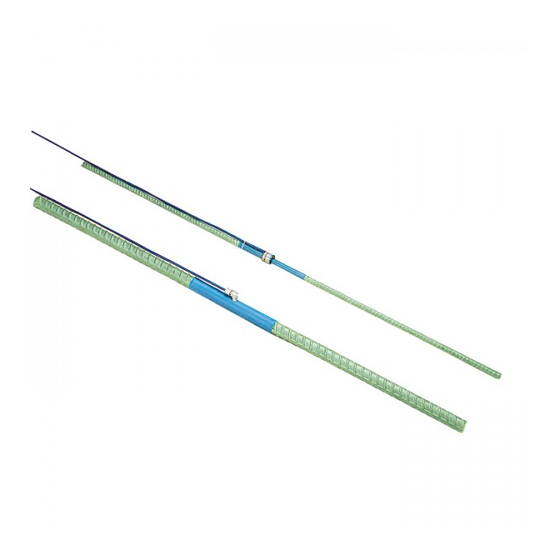
Models 4911/4911A
Vibrating Wire Rebar Strain Meters
No part of this instruction manual may be reproduced, by any means, without the written consent of Geokon
®
.
The information contained herein is believed to be accurate and reliable. However, Geokon
®
assumes no responsibility for errors,
omissions or misinterpretation. The information herein is subject to change without notification.
Copyright © 1989-2019 by Geokon
®
(Doc Rev R, 1/03/2019)
Advertisement
Table of Contents

Related Manuals for Geokon 4911


Summary of Contents for Geokon 4911
- Page 1 Installation Manual Models 4911/4911A Vibrating Wire Rebar Strain Meters No part of this instruction manual may be reproduced, by any means, without the written consent of Geokon ® The information contained herein is believed to be accurate and reliable. However, Geokon ®...
- Page 3 Geokon or any breach of any warranty by Geokon shall not exceed the purchase price paid by the purchaser to Geokon for the unit or units, or equipment directly affected by such breach. Under no circumstances will Geokon reimburse the claimant for loss incurred in removing and/or reinstalling equipment.
-
Page 5: Table Of Contents
TABLE of CONTENTS 1. INTRODUCTION ..............................1 2. INSTALLATION ..............................2 2.1 P ............................. 2 RELIMINARY 2.2 I 4911, “S ” ......................2 NSTALLING ODEL ISTER 2.3 I 4911A ..........................4 NSTALLING ODEL 2.4 C ............................5 ABLE NSTALLATION 2.5 C ........................ - Page 6 FIGURES 1 - M 4911 R ......................1 IGURE ODEL EBAR TRAIN ETER 2 - M 4911A R ......................1 IGURE ODEL EBAR TRAIN ETER 3 - M 4911 “S ” I ....................3 IGURE ODEL ISTER NSTALLATION 4 - M 4911 “S...
-
Page 7: Introduction
It is designed to be wire tied in parallel with structural rebar. The small diameter of the 4911 minimizes its affect on the sectional modulus of the concrete. The cable exits the strain meter through a small block of protective epoxy. -
Page 8: Installation
Resistance between any conductor and the shield should exceed two megohms. If the strain meter fails any of the preliminary tests, see Section 5 for troubleshooting. 2.2 Installing Model 4911, “Sister Bar” Sister Bars are usually installed using standard iron tie wire. Ties near the ends and at the one- third points are sufficient if the gauge is being wired to a larger section of rebar or to horizontal bars. -
Page 9: Figure 3 - Model 4911 "Sister
Figure 3 - Model 4911 “Sister Bar” Installation Figure 4 - Model 4911 “Sister Bar” Installation Detail... -
Page 10: Installing Model 4911A
(one-meter) using nylon cable ties. Avoid using iron tie wire to secure the cable as the cable could be cut. Figure 5 show a typical 4911 installation. Be sure to note the location and serial numbers of all instruments during the installation process. -
Page 11: Cable Installation
2.5 Cable Splicing and Termination Terminal boxes with sealed cable entries are available from Geokon for all types of applications. These allow many gauges to be terminated at one location with complete protection of the lead wires. -
Page 12: Figure 6 - Recommendedl
Terminal boxes and multiplexers available from Geokon provide locations for the installation of these components. Lighting arrestor boards and enclosures are also available from Geokon. These units install • where the instrument cable exits the structure being monitored. The enclosure has a removable top to allow the customer to service the components or replace the board in the event that the unit is damaged by a lightning strike. -
Page 13: Taking Readings
3. TAKING READINGS 3.1 GK-404 Readout Box The GK-404 is a palm sized readout box, which displays the vibrating wire value and the temperature in degrees centigrade. 3.1.1 Operating the GK-404 Before use, attach the flying leads to the GK-404 by aligning the red circle on the silver “Lemo”... -
Page 14: Gk-405 Readout Box
3.2.2 Connecting Sensors with Bare Leads Attach the GK-403-2 flying leads to the bare leads of a Geokon vibrating wire sensor by connecting each of the clips on the leads to the matching colors of the sensor conductors, with blue representing the shield (bare). -
Page 15: Gk-403 Readout Box (Obsolete Model)
3.3.2 Connecting Sensors with Bare Leads Attach the GK-403-2 flying leads to the bare leads of a Geokon vibrating wire sensor by connecting each of the clips on the leads to the matching colors of the sensor conductors, with blue representing the shield (bare). -
Page 16: Measuring Temperatures
3.4 Measuring Temperatures All vibrating wire strain meters are equipped with a thermistor, which gives a varying resistance output as the temperature changes. The white and green leads of the instrument cable are normally connected to the internal thermistor. The GK-403, GK-404, and GK-405 readout boxes will read the thermistor and display the temperature in degrees C. -
Page 17: Data Reduction
4. DATA REDUCTION 4.1 Strain Calculation The basic units utilized by Geokon for measurement and reduction of data are “digits”. Calculation of digits is based on the following equation: Digits = � � x 10 or Digits= 1000 Equation 1 - Digits Calculation Where;... - Page 18 Because of the difference in these two coefficients, a correction is required to the apparent strains, equal to the difference of the two coefficients. The equation for this correction is as follows: ε load related = ((R ) × C) + ((T ) ×...
-
Page 19: Environmental Factors
4.3 Environmental Factors Since the purpose of the strain meter installation is to monitor site conditions, factors which may affect these conditions should always be observed and recorded. Seemingly minor effects may have a real influence on the behavior of the structure being monitored, and may give an early indication of potential problems. -
Page 20: Troubleshooting
Gauges should not be opened in the field. Should difficulties arise, consult the following list of problems and possible solutions. Return any faulty gauges to the factory. For additional troubleshooting and support contact Geokon. Symptom: Thermistor resistance is too high ... -
Page 21: Table 2 - Sample Resistance
Vibrating Wire Sensor Lead Grid - SAMPLE VALUES Black White Green Shield infinite infinite infinite ≅50Ω Black infinite infinite infinite ≅50Ω 3000Ω at White infinite infinite infinite 25°C 3000Ω at Green infinite infinite infinite 25°C Shield infinite infinite infinite infinite Table 2 - Sample Resistance Vibrating Wire Sensor Lead Grid - SENSOR NAME/## : Black... -
Page 22: Appendix A. Specifications
Two twisted pair (Four conductor) 22 AWG Electrical Cable: Foil shield, PVC jacket, nominal OD=6.3 mm (0.250") Table 4 - Model 4911A/4911 Strain Meter Specifications Notes: The standard factory setting allows for 2000 µε in compression and 1000 µε in tension. Other initial settings available upon request. -
Page 23: Appendix B. Thermistor Temperature Derivation
APPENDIX B. THERMISTOR TEMPERATURE DERIVATION Thermistor Type: YSI 44005, Dale #1C3001-B3, Alpha #13A3001-B3 Resistance to Temperature Equation: A+B ( LnR ) +C(LnR) -273.2 Equation 6 - Resistance to Temperature Where; T = Temperature in °C. LnR = Natural Log of Thermistor Resistance. A = 1.4051 ×... -
Page 24: Appendix C. Deriving The Calibration Factor (C) From The Test Data
APPENDIX C. DERIVING THE CALIBRATION FACTOR (C) FROM THE TEST DATA Geokon Rebar Strain Meters are calibrated by loading them in a testing machine; hence, the gauge factor (C) must be determined after converting loads to strains. This is done as follows: The central section of the rebar strain meter, (the unbonded length) which is 7.5"... -
Page 25: Table 6 - Unbonded Sectiond
ε ×E Equation 8 - Zone Two Calculation ε ×E Equation 9 - Zone Three Calculation Where; P is the load in pounds or kilograms. a 2 and a 3 are the cross-sectional areas in inches 2 or cm 2 . See Table 6. Ε... -
Page 26: Table 7 - Microstrain Conversion
By making the various substitutions of Table 6 the relationship between strain in the unbonded section versus change in readout digits can be obtained. Using the #6 rebar as an example, with English conventions, yields the following: ... -
Page 27: Appendix D. Sample Calibration Report
APPENDIX D. SAMPLE CALIBRATION REPORT Figure 10 - Sample Model 4911 Calibration Report...
Need help?
Do you have a question about the 4911 and is the answer not in the manual?
Questions and answers