Advertisement
Use this troubleshooting supplement to help:
Measure DC voltage test points to identify major discrepancies and locate problem areas.
(Keep in mind that the voltage measurements will vary slightly from kit to kit. The voltages you measure should be in
the same ballpark, but do not expect to get the exact same value.)
Test Point
Location Description
1
Transistor Collector
2
3
4
5
You must plug a guitar cable into the input jack when taking the voltage measurements
because the input jack is set up to disconnect power from the circuit when unplugged.
Using a volt meter, connect the ground side lead of the meter to any ground point on the pedal.
One convenient ground point would be the output jack's ground lug. The other volt meter lead will
be used to measure DC voltage at the test points listed above and shown in the drawing on the next
page.
Transistor Base
Transistor Emitter
Power
LED Anode (+)
Voltage Measurement
3.1 VDC
0.6 VDC
0.0 VDC
8.9 VDC
2 VDC
-
+
Your Unit's Voltages
Advertisement
Table of Contents

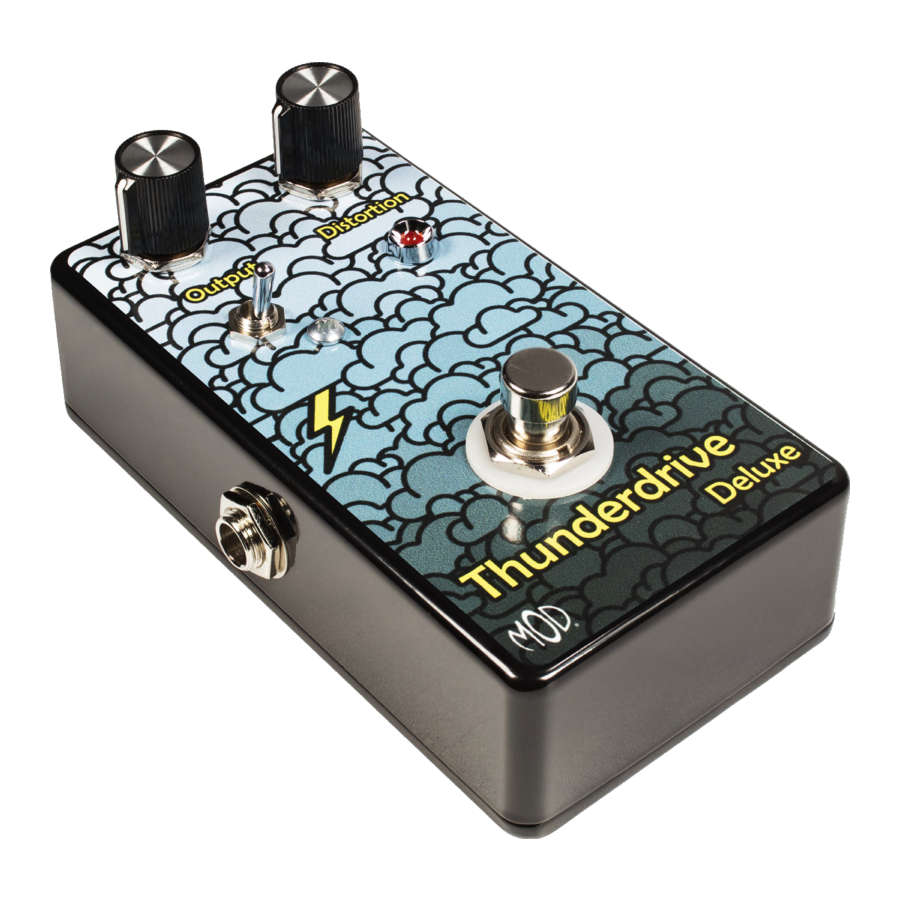
Summary of Contents for Mod Thunderdrive Deluxe
- Page 1 Use this troubleshooting supplement to help: Measure DC voltage test points to identify major discrepancies and locate problem areas. (Keep in mind that the voltage measurements will vary slightly from kit to kit. The voltages you measure should be in the same ballpark, but do not expect to get the exact same value.) Your Unit’s Voltages Test Point...
- Page 2 DISTORTION OUTPUT Guitar cable must be plugged into the input jack while taking voltage measurements INPUT JACK OUTPUT JACK DC Voltage Test Points...
- Page 3 DISTORTION OUTPUT Guitar cable must be plugged into the input jack while taking voltage measurements mVAC INPUT JACK OUTPUT JACK mVAC AC Voltage Test Points (Distortion set to Max)
- Page 4 Continuity Tests With your meter set to check continuity, check the footswitch terminal continuity to make sure it is switching correctly. DISTORTION OUTPUT 3PDT Foot Switch Guitar cable must be plugged into the input jack while taking voltage measurements Switching function of the 3PDT switch. The solid line illustrates an internal connection between terminals.


Need help?
Do you have a question about the Thunderdrive Deluxe and is the answer not in the manual?
Questions and answers