Table of Contents
Advertisement
Quick Links
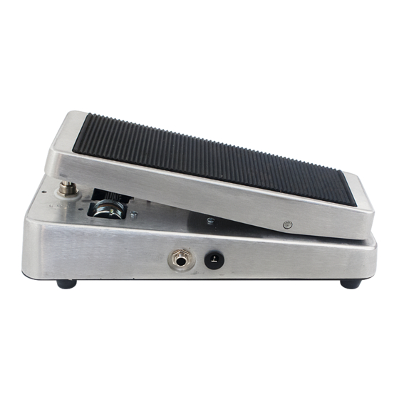
THE WAHTZ WAH (K-985)
Output
9 VDC
Jack
CENTER (-)
Unplug from the Wahtz input
ADAPTER
jack (other side) when not in
use to save battery life.
Use these instructions to learn:
How to build a wah-wah pedal
The Wahtz Wah Pedal produces the classic wah tone you've come to expect with a hint of extra bite and
growl. True bypass switching insures no loss of signal when the wah effect is not engaged, and the long life
potentiometer manufactured specifically for use in wah pedals is included to provide years of smooth, quiet
operation. Point to point construction allows advanced kit builders to easily experiment with modifications to
further tailor the tone to more individual tastes.
Warning: This circuit was designed for use with a 9 VDC power supply only.
1
Copyright © 2016 by modkitsdiy.com
Advertisement
Table of Contents

Related Manuals for Mod WAHTZ WAH K-985


Summary of Contents for Mod WAHTZ WAH K-985
- Page 1 THE WAHTZ WAH (K-985) Output 9 VDC Jack CENTER (-) Unplug from the Wahtz input ADAPTER jack (other side) when not in use to save battery life. Use these instructions to learn: How to build a wah-wah pedal The Wahtz Wah Pedal produces the classic wah tone you've come to expect with a hint of extra bite and growl.
-
Page 2: Table Of Contents
TABLE OF CONTENTS TOOL LIST p. 2 PARTS LIST DRAWINGS pp. 3 - 5 Wah Shell Parts p. 3 Electronic Components & Additional Hardware p. 4 SOLDERING TIPS p. 6 STEP BY STEP ASSEMBLY INSTRUCTIONS pp. 7 - 13 Section 1 - Wah Shell Assembly p. -
Page 3: Parts List Drawings
PARTS LIST 1 Rack Assembly Parts: Treadle Rack Front Bumpers P-ECB-RACK Wah Base Rear Bumper Small Screw (M3 x 0.5, L = 12 mm) Felt Switch Pad Bottom Cover K-PWAH-FELT Hex Nut (M3 x 0.5) Rubber Tread Split Lock Washer Rubber Feet, Mounting Screws Rack mount... -
Page 4: Electronic Components & Additional Hardware
PARTS LIST 2 0.01µF Capacitor 400V DPDT Foot Switch Double Sided Adhesive Foam Tape C-TD01-400 P-H498 103K 400V 0.22µF Capacitor 100V C-PEID22-100 DC Power Jack S-H750 Foam Battery Cushion Battery Clip 4.7µF Polarized Capacitor 35V S-H155 K-PC4D7-35 4.7µF35V Stranded Wire (22 AWG) - White K-PUL1569-WHITE (5 FT) #4 Screws (3/8"... - Page 5 PARTS LIST 3 270 Ω Resistor ½ W 100kΩ Resistor ½ W R-A270 R-A100K 100K brown violet black brown yellow gold gold 1kΩ Resistor ½ W 470kΩ Resistor ½ W R-A1K R-A470K 470K brown yellow black violet yellow gold gold 1.5kΩ...
-
Page 6: Soldering Tips
SOLDERING TIPS It is important to make a good solder joint at each connection point. A cold solder joint is a connection that may look connected but is actually disconnected or intermittently connected. (A cold solder joint can keep your project from working.) Follow these tips to make a good solder joint. -
Page 7: Step By Step Assembly Instructions
SECTION 1 - Wah Shell Assembly If you plan on painting the enclosure, do so prior to assembly and allow plenty of time for the paint to dry. Rack Assembly and Bumpers On the treadle, use two of the self tapping screws and split lock washers to fasten the rack mount to its mounting block in the same orientation as shown in the drawing. -
Page 8: Section 2 - Mounting Large Components To The Base
Mount the L-bracket on the outer surface of the base Bearing Pin Mount using the two long 16 mm screws, nuts and flat washers as shown in the drawing. The screws should be inserted from the inside of the base so that the screw L-bracket heads are on the inside of the pedal. -
Page 9: Section 3 - Final Assembly Of Pedal Base And Treadle
Mount the wah pot on its mounting bracket with solder lugs facing up as shown in Drawing 1. Be sure to press the pot all the way down to rest against the bottom of the bracket. The pot's nut and small flat washer will be on the input jack side of the mounting bracket. The lock washer and two large washers will be on the output jack side of the mounting bracket. -
Page 10: Section 4 - Wiring The Jacks, Pots, Footswitch And Terminal Strips
SECTION 4 - Wiring the Jacks, Pots, Footswitch and Terminal Strips Please refer to DRAWING 2 Stripping and tinning wire: Throughout these instructions you will be told to strip and tin a length of wire numerous times. Unless noted otherwise, cut the wire to the length stated in the instructions. - Page 11 2) Mount the inductor with double sided foam tape. Cut a ½" x ½" piece of double sided foam tape, remove the backing from one side and press it on to the flat side of the inductor. Remove the backing from the other side of this piece of tape and fasten the inductor to the enclosure surface as shown in Drawing 3.
-
Page 12: Section 6 - Final Assembly
18) Mount one 2N5088 transistor to Terminals #5, #6 and #7. 5088 Terminals #5: Collector Terminals #6: Base Terminals #7: Emitter E B C 19) Mount the remaining 2N5088 transistor to Terminals #12, #13 and #14. Terminals #12: Collector 5088 Terminals #13: Base Terminals #14: Emitter E B C... -
Page 13: Adjustment Of The Footswitch Height
GROUND Installing the Foam Battery Cushion TIP LUG Locate the remaining piece of double sided foam tape and the gray foam battery cushion. This will be installed to keep the battery in place. 103K 400V Remove the backing from one side of the foam tape and attach to the inside of the wah base at the heel end roughly centered about 1"... -
Page 14: Assembly Drawings (3 Drawings)
DRAWING 1 INSIDE VIEW OF THE BASE ENCLOSURE RING LUG GROUND LUG Input Jack Output Jack GROUND TIP LUG DC Power Jack... - Page 15 DRAWING 2 INSIDE VIEW OF THE BASE ENCLOSURE RING LUG GROUND LUG Input Jack Output Jack GROUND TIP LUG DC Power Jack...
- Page 16 DRAWING 3 INSIDE VIEW OF THE BASE ENCLOSURE RING LUG GROUND LUG 100K Input Jack Output Jack GROUND TIP LUG DC Power 103K Jack 400V Black...
Need help?
Do you have a question about the WAHTZ WAH K-985 and is the answer not in the manual?
Questions and answers