Advertisement
Quick Links
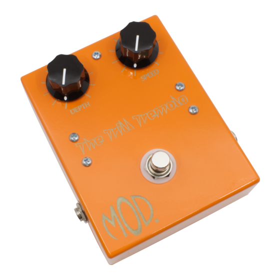
THE TRILL TREMOLO (K-960)
DEPTH
SPEED
The Trill Tremolo
Unplug when not in use
to save battery life.
Modkitsdiy.com
TO
FROM
AMP
GUITAR
IN
OUT
Use these instructions to learn:
How to build an effects pedal for tremolo.
The Trill Tremolo pedal offers classic tremolo tones in an easy to build kit. The Speed knob provides a wide
range from very slow to a rapid fire effect. The Depth knob varies the ratio between effected and dry signal.
Using modern, low noise transistors makes operation of the Trill quiet with no signal drop when engaged as
in some vintage style tremolo pedals.
Warning: This circuit was designed for use with a 9 VDC power supply only.
www.modkitsdiy.com
1
Copyright © 2012 by modkitsdiy.com
Advertisement

Related Manuals for Mod Trill Tremolo


Summary of Contents for Mod Trill Tremolo
- Page 1 How to build an effects pedal for tremolo. The Trill Tremolo pedal offers classic tremolo tones in an easy to build kit. The Speed knob provides a wide range from very slow to a rapid fire effect. The Depth knob varies the ratio between effected and dry signal.
-
Page 2: Table Of Contents
TABLE OF CONTENTS TOOL LIST ……………………………………………………………………………………….2 PARTS LIST DRAWINGS……………………………………………………………………...3, 4 SOLDERING TIPS ……………………………………………………………………………….5 STEP BY STEP ASSEMBLY INSTRUCTIONS ……………………………………………….6 Section 1 – Mount Potentiometers, Terminal Strips and Footswitch ……………………6 Section 2 – Mount Input & Output Capacitors, ¼” Jacks and Wire the Footswitch ………..6 Section 3 –... -
Page 3: Parts List Drawings
PARTS LIST 1 Stranded Wire (22 AWG) - Red DPDT Foot Switch K-PUL1569 (3 FT) P-H498 Enclosure P-H1590BCE-O Potentiometers: 1ML and 250KL R-VA1ML R-VA250KL Knob (Black with Line) P-K345 Terminal Strip with 5 Terminals P-0501H01 Battery Clip S-H155 Terminal Strip with 8 Terminals P-0802H ¼”... - Page 4 PARTS LIST 2 NPN BJT (MPSA18) 1.5k Resistor ½ W P-QMPSA18 R-A1D5K 1.5K brown green gold E B C 10 F Polarized Capacitor 50V 15k Resistor ½ W C-ET10-50 R-A15K 10 F 50V brown green orange gold 0.1 F Capacitor 100V 3M Resistor ½...
-
Page 5: Soldering Tips
SOLDERING TIPS It is important to make a good solder joint at each connection point. A cold solder joint is a connection that may look connected but is actually disconnected or intermittently connected. (A cold solder joint can keep your project from working.) Follow these tips to make a good solder joint. -
Page 6: Step By Step Assembly Instructions
SECTION 1 – Mount Potentiometers, Terminal Strips and Footswitch Please refer to DRAWING 1 and DRAWING 2. Alignment Orient the box with ½” hole nearest you. Bend back and remove the alignment tab on the top of each potentiometer using a pair of pliers before mounting the pots so that they can mount flush against the enclosure surface. -
Page 7: Section 3 - Strip, Tin And Connect The Remaining Wires
Mount the output jack in the 3/8" hole on the right side of the box. Make sure the “tip” lug of the input jack is facing up towards the enclosure opening. Stripping and tinning wire and soldering. Throughout these instructions you will be told to strip and tin a length of wire numerous times. -
Page 8: Section 4 - Mount The Components
SECTION 4 – Mount the Components Please refer to DRAWING 5. Connect the 1.5K resistor to Terminals #1 & #4. Connect a 100K resistor to Terminals #2 & #3. Only solder the connection at Terminal #2 at this point. (There will be two more components connected to Terminal #3). Connect the 0.1 F capacitor to Terminals #3 &... - Page 9 Connect another 100K resistor to Terminals #18 & #19. Only solder the #18 connection, now. (There will be three more components added to #19). Connect the 3M resistor to Terminals #19 & #20. Do not solder these connections, yet. (There will be more components added to each terminal). Mount another MPSA18 transistor to Terminals #19, #20 and #21.
- Page 10 DRAWING 1 1/8" 5/16" 5/16" 1/8" 1/8" INSIDE VIEW OF THE ENCLOSURE 1/8" 1/8" 1/2" 3/8" 3/8" DRAWING 2 SPEED DEPTH 250KL...
- Page 11 DRAWING 3 SPEED DEPTH 250KL INPUT OUTPUT GROUND RING LUG .1 F .1 F GROUND TIP LUG DRAWING 4 SPEED DEPTH 250KL .1 F .1 F...
- Page 12 DRAWING 5 SPEED DEPTH 250KL .22 F 100K .22 F 100K .22 F 1.5K .1 F 100K .1 F .1 F DRAWING 6 .22 F 100K .22 F MPSA18 100K .22 F MPSA18 1.5K .1 F 100K .1 F .1 F...
Need help?
Do you have a question about the Trill Tremolo and is the answer not in the manual?
Questions and answers