Table of Contents
Advertisement
Quick Links
Advertisement
Table of Contents

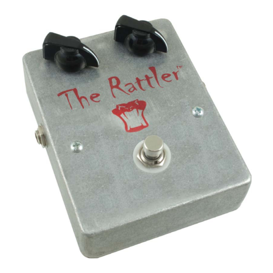
Summary of Contents for Mod The Rattler
- Page 1 Assembly Instructions KITS DIY...
-
Page 2: Kit Contents
Kit Contents: 1 12” Piece Wire 22AWG Standard 2 2N3906 PNP TO-92 Transistors 2 1N414A Diodes 2 10K ½W 5% Resistors (Brown-Black-Orange) 1 1K Linear Pot 1 82K ½W 5% Resistor (Gray-Red-Orange) 1 10μF Axial Lead Electrolytic Capacitor 1 10K Linear Pot 1 Aluminum Chassis with Bottom Plate &... -
Page 3: Before You Start
Before You Start: • Use the parts list to confi rm that all parts are included with your kit. • Be sure to have the required tools ready and easily accessible. • Read this entire instruction manual and be certain to read each step completely before beginning the assembly to familiarize yourself with the process. - Page 4 Prepare Terminal Strip Sub-Assembly: Note: For ease of construction, the Terminal Strip sub-assembly is built before mounting in chassis. Refer to fi gure 2 for proper placement of components. Place parts with component leads secured to solder lugs as described, but do not solder connections until all parts are connected. When soldering connections with transistor or diode leads, use the heatsink to prevent component damage.
- Page 5 Twist leads together and solder “Banded” ends of diodes Figure 3: Diodes detail Connect the 0.1μF capacitor to lug #5 of the terminal strip and lug #1 of the 10kΩ potentiometer. Solder both connections using the heatsink. Trim excess leads. Connect the 0.1μF capacitor (see note below) to lug #2 of the terminal strip and lug #3 of the footswitch.
-
Page 6: Final Assembly
Tighten the chicken-head set-screws (don’t over-tighten please). Warning: The Rattler is one vicious beast of a box. It will scare your friends, irritate neighbors, and blow away chumps using those other wimpy boxes. Use with discretion! -
Page 10: Troubleshooting Steps
Have you assembled your Rattler kit, double-checked your work and can’t get any sound to come out when plugged in? Here are some very simple checks to make when beginning troubleshooting. Believe it or not, these checks are frequently overlooked upon fi rst plugging in the Rattler. 1.) Is the 9 volt battery fully charged and connected? 2.) Are your guitar and amp plugged in to the correct jacks? -
Page 11: Soldering Tips
Soldering Tips: It is important to make a good solder joint at each connection point. A cold solder joint is a connection that may look connected but is actually disconnected or intermittently connected. (A cold solder joint can keep your project from working). Follow these tips to make a good solder join. - Page 12 4.) Be sure to adequately cover both the component lead and the connection point with melted solder. • Remove the soldering iron from your work and allow the solder joint to cool. The solder joint should be shiny and smooth after solidifying. •...
- Page 13 2.) Apply fresh solder to mix in with old solder joint. 3.) Use a de-soldering tool to remove the old solder joint while it is heated.


Need help?
Do you have a question about the The Rattler and is the answer not in the manual?
Questions and answers