Table of Contents
Advertisement
Installation, Operation,
and Maintenance Manual
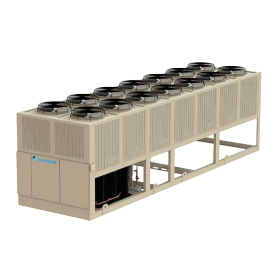
Trailblazer
®
Air-Cooled Scroll Compressor Chillers
With High Efficiency Variable Speed Fan Technology
Model AGZ, E Vintage
30 to 241 Tons (100 to 840 kW)
HFC-410A Refrigerant
50/60 Hz
IOM 1206-13
Group: Chiller
Part Number: IOM1206-13
Date: September 2020
Advertisement
Table of Contents

Related Manuals for Daikin Trailblazer AGZ030-101E


Summary of Contents for Daikin Trailblazer AGZ030-101E
- Page 1 Installation, Operation, IOM 1206-13 and Maintenance Manual Group: Chiller Part Number: IOM1206-13 Date: September 2020 Trailblazer ® Air-Cooled Scroll Compressor Chillers With High Efficiency Variable Speed Fan Technology Model AGZ, E Vintage 30 to 241 Tons (100 to 840 kW) HFC-410A Refrigerant 50/60 Hz...
-
Page 2: Table Of Contents
AHRI ACCL Certification Program. ©2020 Daikin Applied. Illustrations and data cover the Daikin Applied product at the time of publication and we reserve the right to make changes in design and construction at any time without notice. - Page 3 Document Attached: Remote piping approval Notes: The most common problems delaying start-up and affecting unit reliability are: Field installed compressor motor power supply leads too small. Questions: Contact the local Daikin sales representative*. State size, number and type of conductors and conduits installed: From Power supply to chiller * Refer to NFPA 70-2017, Article 440.35...
-
Page 5: Installation And Application Information
WARNING Polyolester Oil, commonly known as POE oil is a synthetic oil used in many refrigeration systems, and may be present in this Daikin product. POE oil, if ever in contact with PVC/CPVC, will coat the inside wall of PVC/CPVC pipe causing environmental stress fractures. - Page 6 15°F to 65°F (-9°C to 18°C) operating envelope; consult Daikin Tools to ensure chiller is capable of the required lift. Operating chilled water delta-T range 6°F to 16°F (3.3°C to 8.9°C) Maximum evaporator operating inlet fluid temperature 81°F (27°C)
- Page 7 Installation and Application Information Figure 2: Compresssor Base Plate Mounting DANGER Improper rigging, lifting, or moving of a unit can result in property damage, severe personal injury or death. Follow rigging and moving instructions carefully. Do not stand beneath the unit while it is lifted or being installed. Figure 1: Required Lifting Arrangement NOTE: Number of fans and...
- Page 8 Installation and Application Information Operational Spacing Requirements Case 2: Two Units, Side-by-Side Sufficient clearance must be maintained between the unit For models 030-180, there must be a minimum of 4 feet and adjacent walls or other units to allow the required unit air between two units placed side-by-side;...
- Page 9 Installation and Application Information Case 3: Three or More Units, Side-by-Side Case 4: Open Screening Walls For all models, there must be a minimum distance between Decorative screening walls are often used to help conceal a any units placed side-by-side; however, performance may be unit either on grade or on a rooftop.
- Page 10 Have any pit installation reviewed by the Daikin Applied sales representative prior to installation to ensure it has sufficient air-flow characteristics and approved by the installation design engineer to avoid risk of accident.
- Page 11 Installation and Application Information Models AGZ140-241E: The Case 5 figures for models AGZ140-241E show adjustment factors for pit/wall heights of 6 feet, 8 feet, and 10 feet. Figure 17: Case 5 - Full Load Capacity Reduction Figure 19: Case 5 - Power Increase (AGZ140-180E) (AGZ140-211E) Power Increase (AGZ140-211E)
- Page 12 Daikin product. POE oil, if ever in contact with PVC/CPVC, will Field installed water piping to the chiller must include: coat the inside wall of PVC/CPVC pipe causing environmental stress fractures.
- Page 13 Installation and Application Information Inlet Strainer Guidelines Figure 23: Factory Installed Strainer An inlet water strainer kit must be installed in the chilled water piping before the evaporator inlet. Several paths are available to meet this requirement: 1. Factory installed option is available - models 030 to 241. 2.
- Page 14 Strainers must be used to drop adjustment factors. protect the chiller systems from water-borne debris. Daikin will not be responsible for any water-borne debris damage or water Chilled Water Pump side damage to the chiller heat exchangers due to improperly treated water.
- Page 15 There is also a set of paddle switch contacts on the switch that envelope; consult with a Daikin Applied sales representative to can be used for an indicator light or an alarm to indicate when ensure chiller is capable of the required lift.
- Page 16 Partial Heat Recovery Freeze Avoidance operating temperatures, and the water flow rate through the auxiliary heat exchangers. Contact a local Daikin Applied sales The heat recovery condenser is insulated; a factory-installed representative for information on specific applications.
- Page 17 Installation and Application Information Figure 24: AGZ075-241E Heat Recovery Field Piping AGZ075-241E PACKAGE CHILLER BACK END OF UNIT WITH HEAT RECOVERY MICROCHANNEL ALUMINUM COIL *FIELD INSTALLED HEAT RECOVERY LOOP FIELD CONNECTIONS 334549813 THERMOMETER VIBRATION (USER OPTION) ELIMINATOR VIBRATION ELIMINATOR INLET WATER STRAINER TEE CONNECTION &...
-
Page 18: Refrigerant Schematics
Refrigerant Schematics Refrigerant Schematics Figure 26: AGZ030-070E Package Chiller with Microchannel IOM 1206-13 • TRAILBLAZER MODEL AGZ CHILLERS www.DaikinApplied.com ®... - Page 19 Refrigerant Schematics Figure 27: AGZ075-101E Package Chiller with Microchannel www.DaikinApplied.com IOM 1206-13 • TRAILBLAZER MODEL AGZ CHILLERS ®...
- Page 20 Refrigerant Schematics Figure 28: AGZ110-130E Package Chiller with Microchannel IOM 1206-13 • TRAILBLAZER MODEL AGZ CHILLERS www.DaikinApplied.com ®...
- Page 21 Refrigerant Schematics Figure 29: AGZ140-180E Package Chiller with Microchannel www.DaikinApplied.com IOM 1206-13 • TRAILBLAZER MODEL AGZ CHILLERS ®...
- Page 22 Refrigerant Schematics Figure 30: AGZ191-241E Package Chiller with Microchannel IOM 1206-13 • TRAILBLAZER MODEL AGZ CHILLERS www.DaikinApplied.com ®...
- Page 23 Refrigerant Schematics Figure 31: AGZ75-241E Package Chiller with Microchannel and Heat Recovery www.DaikinApplied.com IOM 1206-13 • TRAILBLAZER MODEL AGZ CHILLERS ®...
-
Page 24: Dimensions And Weights - Packaged Units
Dimensions and Weights - Packaged Units Dimensions and Weights - Packaged Units Figure 32: AGZ030E - AGZ035E, 4 Fan Models IOM 1206-13 • TRAILBLAZER MODEL AGZ CHILLERS www.DaikinApplied.com ®... - Page 25 Dimensions and Weights - Packaged Units Figure 33: AGZ040E - AGZ070E, 4 Fan Models www.DaikinApplied.com IOM 1206-13 • TRAILBLAZER MODEL AGZ CHILLERS ®...
- Page 26 Dimensions and Weights - Packaged Units Figure 34: AGZ075E - AGZ101E, 6 Fan Models IOM 1206-13 • TRAILBLAZER MODEL AGZ CHILLERS www.DaikinApplied.com ®...
- Page 27 Dimensions and Weights - Packaged Units Figure 35: AGZ110E - AGZ130E, 8 Fan Models www.DaikinApplied.com IOM 1206-13 • TRAILBLAZER MODEL AGZ CHILLERS ®...
- Page 28 Dimensions and Weights - Packaged Units Figure 36: AGZ140E - AGZ161E, 10 Fan Models IOM 1206-13 • TRAILBLAZER MODEL AGZ CHILLERS www.DaikinApplied.com ®...
- Page 29 Dimensions and Weights - Packaged Units Figure 37: AGZ170E - AGZ180E, 10 Fan Models www.DaikinApplied.com IOM 1206-13 • TRAILBLAZER MODEL AGZ CHILLERS ®...
- Page 30 Dimensions and Weights - Packaged Units Figure 38: AGZ191E, AGZ211E, 12 Fan Models IOM 1206-13 • TRAILBLAZER MODEL AGZ CHILLERS www.DaikinApplied.com ®...
- Page 31 Dimensions and Weights - Packaged Units Figure 39: AGZ226E - AGZ241E, 14 Fan Models www.DaikinApplied.com IOM 1206-13 • TRAILBLAZER MODEL AGZ CHILLERS ®...
-
Page 32: Dimensions And Weights - Heat Recovery Units
Dimensions and Weights - Heat recovery Units Dimensions and Weights - Heat recovery Units Figure 40: AGZ075E - AGZ101E, Heat Recovery Units, 6 Fan Models IOM 1206-13 • TRAILBLAZER MODEL AGZ CHILLERS www.DaikinApplied.com ®... - Page 33 Dimensions and Weights - Heat recovery Units Figure 41: AGZ110E - AGZ130E, Heat Recovery Units, 8 Fan Models www.DaikinApplied.com IOM 1206-13 • TRAILBLAZER MODEL AGZ CHILLERS ®...
- Page 34 Dimensions and Weights - Heat recovery Units Figure 42: AGZ140E - AGZ161E, Heat Recovery Units, 10 Fan Models IOM 1206-13 • TRAILBLAZER MODEL AGZ CHILLERS www.DaikinApplied.com ®...
- Page 35 Dimensions and Weights - Heat recovery Units Figure 43: AGZ170E - AGZ180E, Heat Recovery Units, 10 Fan Models www.DaikinApplied.com IOM 1206-13 • TRAILBLAZER MODEL AGZ CHILLERS ®...
- Page 36 Dimensions and Weights - Heat recovery Units Figure 44: AGZ191E - AGZ211E with Heat Recovery, 12 Fan Models IOM 1206-13 • TRAILBLAZER MODEL AGZ CHILLERS www.DaikinApplied.com ®...
- Page 37 Dimensions and Weights - Heat recovery Units Figure 45: AGZ226E - AGZ241E with Heat Recovery, 14 Fan Models www.DaikinApplied.com IOM 1206-13 • TRAILBLAZER MODEL AGZ CHILLERS ®...
-
Page 38: Refrigerant Charge
Refrigerant Charge Refrigerant Charge Table 4: Refrigerant Charge - Microchannel Units Microchannel Coil Unit Operating Charge - lbs (kg) Unit Packaged Units Heat Recovery Units Models Replaceable Core Filter Drier Sealed Filter Drier Replaceable Core Filter Drier Circuit 1 Circuit 2 Circuit 1 Circuit 2 Circuit 1... -
Page 39: Isolator Information
24. Optional seismic isolator .56 [14.3] information begins on page 41. Contact a Daikin Applied .25 [6.4] sales representative for isolator information related to units with ELASTOMERIC PAD other fin materials. Table 5: Isolator Kits - Packaged Units... - Page 40 Isolator Information Table 6: Isolator Information - Microchannel Units Rubber-In-Shear (RIS) Mounts Spring Isolator Mountings AGZ-E Model Dark Dark Brown Brown Brown Brown Black Black Green Purple Dark Dark Brown Brown Brown Brown Black Black Green Purple Dark Dark Brown Brown Brown Brown...
- Page 41 Isolator Information Table 7: Isolator Kits - Heat Recovery Units Microchannel - Heat Recovery Units AGZ-E Model Spring Isolators RIS Isolators 075/076 332320117 332325101 080/081 332320117 332325101 090/091 332320117 332325101 100/101 332320117 332325101 332320123 332325113 332320123 332325113 332320123 332325113 332320119 332325113 332320119 332325113...
- Page 42 Isolator Information Figure 48: Seismic Spring Isolators 1 1/8 [29] [203] 13/16 [21] DIA HOLE FOR ATTACHMENT TO CONCRETE (6 TYP) (BASE PLATE) [19] DIA HOLE FOR ATTACHMENT TO 2 1/4 [57] STEEL (4 TYP) (VIEW CUT AWAY FOR CLARITY) 6 1/4 [159] 2 7/8 [73] 2 7/8 [73]...
-
Page 43: Pressure Drop Data
Pressure Drop Data Pressure Drop Data Figure 50: Evaporator Pressure Drop Curves (refer to data table on following page) Flow Rate (gpm) Flow Rate (gpm) www.DaikinApplied.com IOM 1206-13 • TRAILBLAZER MODEL AGZ CHILLERS ®... - Page 44 Pressure Drop Data Table 11: Evaporator Pressure Drop Data Part Load Flow System Only Full Load Flow System Only Fixed and Variable Flow Systems Minimum Flow Rate Minimum Flow Rate Nominal Flow Rate Maximum Flow Rate Curve Model Ref. DP ft. DP kpa DP ft.
- Page 45 Pressure Drop Data Figure 51: Pressure Drop Curves- Heat Recovery Auxilliary Heat Exchangers (refer to data in Table 20.0 18.0 16.0 14.0 12.0 10.0 50.0 100.0 150.0 200.0 250.0 Flow Rate (gpm) Pressure Drop Data-- Heat Recovery Auxilliary Braze Plate Heat Exchangers Table 12: Minimum Flow Nominal Flow...
- Page 46 Pressure Drop Data Table 13: Strainer Pressure Drop AGZ030-070E, 2.5” Strainer Flow (gpm) Pr. Drop (ft) 40.0 60.0 100.0 150.0 300.0 16.1 Table 14: Strainer Pressure Drop AGZ075-130E, 3” Strainer Flow (gpm) Pr. Drop (ft) 50.0 100.0 200.0 300.0 400.0 16.1 Table 15: Strainer Pressure Drop AGZ140-180E, 4”...
-
Page 47: Electrical Data
Electrical Data Electrical Data Electrical Connection DANGER Trailblazer ® units can be ordered with either standard multi- Disconnect, lockout and tag all power to the unit before servicing condenser fan motors or compressors. Failure to do point power or optional single point power connections and so can cause bodily injury or death. - Page 48 Electrical Data Figure 52: Typical Packaged Unit Field Wiring Diagram (Single-Point Connection) FIELD WIRING DIAGRAM WITH MICROTECH CONTROLLER PANEL DISCONNECT SWITCH CIRCUIT BREAKER (BY OTHERS) POWER BLOCK 3 PHASE POWER COMPRESSOR(S) SOURCE AND FAN MOTORS EARTH GROUND 120 VAC CHWR1 DISCONNECT PUMP NO.1 RELAY (BY OTHERS)
- Page 49 Electrical Data Figure 53: Typical Packaged Unit Field Wiring Diagram (Multi-Point Connection) FIELD WIRING DIAGRAM WITH MICROTECH CONTROLLER PANEL DISCONNECT SWITCH CIRCUIT BREAKER 1 (BY OTHERS) POWER BLOCK 3 PHASE TO CIRCUIT 1 POWER COMPRESSOR(S) SOURCE AND FAN MOTORS EARTH GROUND Note: Separate grounding is DISCONNECT...
- Page 50 Electrical Data Figure 54: Typical Heat Recovery Unit Field Wiring Diagram (Single-Point Connection with all options shown) FIELD WIRING DIAGRAM WITH MICROTECH CONTROLLER PANEL DISCONNECT SWITCH CIRCUIT BREAKER (BY OTHERS) POWER BLOCK Note: Separate grounding is 3 PHASE POWER COMPRESSOR(S) required if fed from different SOURCE AND FAN MOTORS...
- Page 51 Electrical Data Figure 55: Typical Heat Recovery Unit Field Wiring Diagram (Multi-Point Connection) FIELD WIRING DIAGRAM WITH MICROTECH CONTROLLER PANEL DISCONNECT SWITCH CIRCUIT BREAKER 1 (BY OTHERS) POWER BLOCK 3 PHASE TO CIRCUIT 1 POWER COMPRESSOR(S) SOURCE AND FAN MOTORS Note: Separate grounding is required if fed from different transformers.
-
Page 52: Unit Controller Operation
Unit Controller Operation Unit Controller Operation General Description The MicroTech III controller’s design not only permits Security protection prevents unauthorized changing of the ® the chiller to run more efficiently, but also can simplify setpoints and control parameters. troubleshooting if a system failure occurs. Every MicroTech ®... - Page 53 Unit Controller Operation Controller Inputs and Outputs Table 25: Digital Inputs Description Signal Off Signal On Main Controller Circuit 1 Switch Circuit Disable Circuit Enable Circuit 1 MHP Switch Fault No fault Table 20: Analog Inputs Circuit 1 Motor Fault No fault Protection Description...
- Page 54 Unit Controller Operation EXV Module 1 and 2 These modules will be used only when the expansion valve type is electronic. Table 30: Digital Inputs Description Output Off Output On Circuit 1 or 2 MLP Switch Fault No Fault Heat Recovery Request No Request Request Switch...
- Page 55 Unit Controller Operation Table 35: AGZ-E Models with 1 VFD per Circuit Number of Fans Physical Output Descr . Output Speed 1 UC X5 Fan 11 Fan 11 Fan 11/13 Fan 11/13 Fan 11/13 Fan 11/13 Speed 2 UC X2 Fan Output 1 UC DO3 Fan 12...
- Page 56 Unit Controller Operation Set Points Set points are initially set to the values in the Default column, order to apply a change. If an option is not included on the unit, and can be adjusted to any value in the Range column. the respective set point may not be visible.
- Page 57 Unit Controller Operation Table 39: Unit Level Set Point Defaults and Ranges (continued) Thursday Duration 12 hrs 0 to 24 hrs Friday Start Time 22:00 00:00 to 23:00 Friday Duration 12 hrs 0 to 24 hrs Saturday Start Time 22:00 00:00 to 23:00 Saturday Duration 12 hrs...
- Page 58 Unit Controller Operation Table 41: Evaporator Water Freeze Evaporator Glycol Range 2.2 to 5.6°C (36 to 42.1°F) -28.89 to 5.6°C (-20 to 42.1°F) Table 42: Low Ambient Lockout Fan VFD Configuration Range None 0 to 15.6°C (32 to 60.1°F) 1/cir or 2/cir -23.3 to 15.6°C (-9.9 to 60.1°F) Table 43: Low Evaporator Pressure Available Mode Selection...
- Page 59 Unit Controller Operation Table 46: Unit Test Mode Set Points Description Default Range Test Unit Alarm Output Off, On Test Evaporator Pump Output 1 Off, On Test Evaporator Pump Output 2 Off, On Test Heat Recovery Pump Output Off, On Test Heat Recovery Position/Speed 0.0% 0.0 to 100.0%...
- Page 60 Unit Controller Operation Circuit Level Set Points The settings in this section all exist for each individual circuit. Table 48: Set Points for Individual Circuits Description Default Range Mode/Enabling Circuit mode Enable Disable, Enable, Test Compressor 1 Enable Auto Auto, Off Compressor 2 Enable Auto Auto, Off...
- Page 61 Unit Controller Operation Special Set Point Operation EXV settings are only visible if the unit is configured with electronic expansion valves. The EXV position set point is not changeable unless the unit switch is off. EXV Position set point on each circuit follows the actual EXV position while EXV Control = Auto.
- Page 62 Unit Controller Operation Table 52: Configuration Group 3 Description Default Range Condenser Target - 100% Circuit Capacity 40.56°C (105°F) 40.56 to 46.11°C (105 to 115°F) Condenser Target - 50% Circuit Capacity, 75% Unit Capacity 40.56°C (105°F) 37.78 to 43.33°C (100 to 110°F) Condenser Target - 50% Circuit Capacity, 50% Unit Capacity 32.22°C (90°F) 31.11 to 36.67°C (88 to 98°F)
-
Page 63: Sequence Of Operation
Sequence of Operation Sequence of Operation Figure 57: Unit Sequence of Operation - Cool Mode Unit power up Unit in O state The chiller may be disabled via the unit switch, the remote switch, the keypad enable setting, or the BAS network. In addition, the chiller will be disabled if all circuits are disabled, or if there is a unit alarm. - Page 64 Sequence of Operation Figure 58: Unit Sequence of Operation - Cool Mode (continue) Keep pump output on while chiller is enabled and either running or ready to run. The chiller is now ready to start if enough load is present. If the LWT is not higher than the start up temperature, the unit status will be Auto:Wait for load.
- Page 65 Sequence of Operation Figure 59: Unit Sequence of Operation - Cool Mode (continued) Maintain unit capacity. The unit capacity can be decreasedif the LWTis below the stage down Can less circuits handle temperature. the load? Has the stage down A minimum time must pass between decreases in unit capacity. time delay expired? Compressors will shut o as needed in the order determined by sequencing logic.
- Page 66 Sequence of Operation Figure 60: Unit Sequence of Operation - Ice Mode Unit power up Unit in O state The chiller may be disabled via the unit switch, the remote switch, the keypad enable setting, or the BAS network. In addition, the chiller will be disabled if all circuits are disabled, or if there is a unit alarm.
- Page 67 Sequence of Operation Figure 61: Unit Sequence of Operation - Ice Mode (continued) Pump output remains on while chiller is enabled. If the chiller is waiting on the motor protection delay after powering up, the unit Is Motor Protection status will be O :Motor Protection Delay. delay active? Keep pump output on while chiller is enabled and either...
- Page 68 Sequence of Operation Figure 62: Unit Sequence of Operation - Ice Mode (continued) If the second circuit is not running, it will be started now. The unit will try to keep the load balanced between circuits as the unit capacity is increased. Increase unit capacity.
- Page 69 Sequence of Operation Figure 63: Circuit Sequence of Operation Unit power up When the circuit is in the O state the EXV is in the closed position, compressors are Circuit is in O state o , solenoid valves are closed, and all condenser fans are o . The circuit must be enabled before it can run.
-
Page 70: Unit Functions
Unit Functions Unit Functions The calculations in this section are used in unit level control means the flow that is needed for a 5.56°C (10°F) delta T at full logic or in control logic across all circuits. unit capacity. Evaporator Delta T Table 54: Minimum Flows and Corresponding Maximum Effective Full Capacity Delta T with Variable Flow The evaporator water delta T is calculated as entering water... - Page 71 Unit Functions the Control Band: Table 55: Unit Mode Settings • Start Up Temperature = Stage Up Temperature + Start Up Control Available Delta set point Source Set Mode Input Modes Set Unit Mode Request Point Point • Shutdown Temperature = Stage Down Temperature – Shutdown Delta set point Cool Cool...
- Page 72 Unit Functions T1 - Off to Auto the Low OAT Lockout set point is configurable if the chiller has condenser fan VFD’s. In that case, there are three options: All of the following are required: • Lockout and Stop – chiller will shut down and lockout •...
- Page 73 Unit Functions Unit Status Evaporator Pump Control The displayed unit status should be determined by the For control of the evaporator pumps, three evaporator pump conditions in the following table: control states should be used: Status Conditions Off - No pump on. Auto Unit State = Auto Start –...
- Page 74 Unit Functions LWT Target Freeze Protection To protect the evaporator from freezing, the evaporator pump The LWT Target varies based on settings and inputs. will start if all of the following are true: The base LWT Target is selected as follows: •...
- Page 75 Unit Functions Unit Capacity Control compressor on each circuit shall be left on until each circuit has only one compressor running. Unit capacity control will be performed as described in this section. All unit capacity limits described in following sections Next To Start must be applied as described.
- Page 76 Unit Functions Demand Limit Maximum LWT Pulldown Rate The maximum unit capacity can be limited by a 4 to 20 mA The maximum drop rate for the leaving water temperature shall signal on the Demand Limit analog input. This function is be limited by the Maximum Pulldown Rate set point only when only enabled if the Demand Limit set point is set to ON.
- Page 77 Unit Functions evaporator recirculation time will be limited to 110 seconds This backup chiller sequence is safe for the unit if it has had or less. The evaporator recirculation time set point will not be power applied for the minimum time stated in the operation changed.
- Page 78 Unit Functions the pressure into a safe zone but capacity of the chiller would • 15.56°C ≤Heat Recovery EWT ≤ 60°C be limited. • Heat Recovery LWT≥Heat Recovery EWT + 1.11°C (2°F) If priority is set to ‘capacity’, the fan speed is allowed to exceed •...
- Page 79 Unit Functions 6. Evaporator LWT target must be at least 4.44°C because below that the discharge temperatures are notadequate to support heat recovery operation Heat Recovery Operation Per State When State = Off • Heat Recovery Pump is off • Heat Recovery Position/Speed signal is 0% •...
-
Page 80: Circuit Functions
Circuit Functions Circuit Functions Calculations By Controller Circuit States The circuit will always be in one of four states: Refrigerant Saturated Temperature Off – Circuit is not running Refrigerant saturated temperature shall be calculated from the Preopen – Circuit is preparing to start pressure sensor readings for each circuit. - Page 81 Circuit Functions Circuit Status T6 – Preopen to Off Any of the following are required: The displayed circuit status should be determined by the conditions in the following table:If more than one status is • Unit State = Off enabled at the same time, the hightest numbered status •...
- Page 82 Circuit Functions Cycle Timers Table 62: 2 Fans per Circuit - With 1 Fan VFD per Circuit Circuit 1 A minimum time between starts of the compressor and a Stage minimum time between shutdown and start of the compressor Description Output Fans shall be enforced.
- Page 83 Circuit Functions Table 64: 3 Fans per Circuit - With 1 Fan VFD per Circuit Table 66: 4 Fans per Circuit - Without Fan VFD Circuit 1 Circuit 1 Stage Stage Description Output Fans Description Output Fans Fan Output 1 UC DO3 Fan 11 On On On On Speed Signal 1 UC X5...
- Page 84 Circuit Functions Figure 67: 5 Fans per Circuit - Unit Numbering Schematic Table 71: 5 Fans per Circuit - With 2 Fan VFDs per Circuit Circuit 1 5-Fan Locations and Numbering Stage Description Output Fans Speed Signal 1 UC X5 Fan 11/13 On On On Fan 13 Fan 15...
- Page 85 Circuit Functions Table 73: 6 Fans per Circuit - With 1 Fan VFD per Circuit Circuit 2 Circuit 1 Stage Description Output Fans Stage Description Output Fans Fan Output 1 UC DO7 Fan 21/23 On On On On On Speed Signal 1 UC X5 Fan 11/13 On On On On On Fan Output 2...
- Page 86 Circuit Functions Condenser Target Skipping First Stage There are circumstances where the first condenser stage will The condenser target is selected based on circuit capacity be skipped, so condenser stage would go from 0 to 2: using the condenser target set points. There are set points that establish the condenser target for 33%, 50%, 67%, and If the circuit has 4 fans, or it has 6 fans and no fan VFD’s, 100% capacity.
- Page 87 Circuit Functions VFD’s within a circuit). The speed will normally be controlled which are to be used during this time, so it should select the between the minimum and maximum speed set points using a value from the setting corresponding to the current circuit PID loop.
- Page 88 Circuit Functions Superheat Target Table 78: Maximum Position Range # Compressors Running/Circuit The suction superheat target is selected per the set points Model depending on what capacity the circuit is running at. AGZ030E • If the circuit has two compressors and one is running, the AGZ035E value used is the SSH Target at 50% set point.
-
Page 89: Alarms
Alarms Alarms Evaporator Flow Loss Capacity Overrides – Limits of Operation Trigger: 1: Evaporator Pump State = Run AND Evaporator Flow Digital The following conditions shall override automatic capacity Input = No Flow for time > Flow Proof Set Point AND at least control as described. - Page 90 Alarms Evaporator EWT Sensor Fault Bad Demand Limit Input Trigger: Sensor shorted or open for longer than one second. Trigger: Demand limit input out of range and Demand Limit set point is set to On. For this alarm, out of range is considered to •...
- Page 91 Alarms Low Evaporator Pressure Mechanical High Pressure Switch Trigger: Trigger: Power up start delay is not active and [Mechanical High Pressure switch input is off and Motor Protection input is This alarm should trigger when Freeze time is exceeded, Low on] for longer than one second.
- Page 92 Alarms Alarm Logs least 400mv OR • OAT < 40.56°C (105°F) and sensor input voltage is from Press the alarm button on the controller to go to the alarm 400mv to 4600mv. section. Three alarm sub-sections will appear. Turn the navigating wheel to highlight among them and press the wheel Condenser Pressure Sensor Fault to select.
- Page 93 Alarms Events High Condenser Pressure - Unload Trigger: Situations may arise that require some action from the chiller This event is triggered if all of the following are true: or that should be logged for future reference, but aren’t severe enough to track as alarms.
- Page 94 Alarms A code 1 Alert will open the M2-M1 contacts. The Alert will reset after 30 minutes. Five consecutive Code 1 Alerts will lockout the compressor. Once the module has locked out the compressor, a power cycle or Modbus reset command will be required for the lockout to be cleared.
-
Page 95: Using The Controller
Using the Controller Using the Controller Figure 71: Schematic of Unit Controller The keypad/display consists of a 5-line by 22-character include changeable data fields (setpoints). display, three buttons (keys) and a “push and roll” navigation When the cursor is on a line the highlights will look like this: wheel. - Page 96 O = Operator level Enter PW **** T = Technican/Manager level D = Daikin Applied factory service technician level Entering an invalid password has the same effect as not entering a password. Screen navigational links: Once a valid password has been entered, the controller •...
- Page 97 Using the Controller Figure 76: Controller Keypad Sample Navigation www.DaikinApplied.com IOM 1206-13 • TRAILBLAZER MODEL AGZ CHILLERS ®...
-
Page 98: Fan Vfd Controller
Fan VFD Controller Fan VFD Controller VFD Interface The VFD controller is located in the lower left-hand corner of the unit control panel. It is used to view data including fault and alarm information. No operator intervention on this control is required for normal unit operation. - Page 99 Fan VFD Controller Figure 77: LCD Display Table 80: Display Data Name Display Content MODE Displayed when in Mode Selection. MONITR Displayed when in Monitor Mode. Operation Mode VERIFY Indicates the Verify Menu Menus PRMSET Displayed when in Parameter Setting Mode. A.TUNE Displayed during Auto-Tuning.
- Page 100 Fan VFD Controller Table 81: Alarm Content State Content Illuminated When the drive detects an alarm or error When an alarm occurs Flashing When an oPE is detected When a fault or error occurs during Auto-Tuning Normal operation (no fault or alarm) Table 82: LO/RE LED and RUN LED Indictors Flashing Flashing Quickly...
- Page 101 Fan VFD Controller Table 83: Types of Alarms, Faults, and Errors Type Drive Response When the drive detects a fault: • The digital operator displays text indicating the specific fault and the ALM indicator LED remains lit until the fault is reset. Faults •...
- Page 102 Fan VFD Controller Optional BAS Interface Inverter Output to the Motor The AGZ chiller controller is configured for stand-alone WARNING operation or integration with BAS through an optional Avoid swapping any 2 of the 3 motor lead connections which will communication module.
-
Page 103: Startup And Shutdown Procedures
Complete the pre-start checklist at the front of clips are installed. this manual and return to Daikin Applied prior to startup date. 3. Put System Switch (S1) to the Emergency Stop position. Pre-Startup Checkout 4. - Page 104 • Complete the “Equipment Warranty Registration Form,” found at the end of this manual, within 10 days of start- up in order to comply with the terms of Daikin Limited Figure 78: Thermal Dispersion Flow Switch and Adapter Product Warranty.
- Page 105 Startup and Shutdown Procedures Mounting If needed, the adapter is threaded into the pipe using pipe sealant appropriate for the application. The flow sensor is Figure 79 highlights the position of the electrical connector and mounted onto the adapter using silicone grease. Carefully indentation ‘mark’...
- Page 106 Startup and Shutdown Procedures Table 87: Flow Volume Calculation US GPM at the velocities indicated below Inside Pipe Pipe adjustment Default Size Diameter per '+' or '-' (inch) (inch) 20 cm/sec 30 cm/sec 50 cm/sec 75 cm/sec 100 cm/sec 150 cm/sec 200 cm/sec 250 cm/sec 300cm/sec key input 2.06...
- Page 107 Startup and Shutdown Procedures 3. When power is initially applied to the flow switch, all green LEDs light and go out step by step. During this time, the output is closed. The unit is in the operating mode. 4. When making manual adjustments to the set point (SP), if no button is pressed for 2 seconds, the unit returns to the operating mode with the newly set value.
-
Page 108: Unit Maintenance
Unit Maintenance General Unit Maintenance the unlikely occurrence of a coil leak, contact Daikin Applied to receive a replacement coil module. On initial start-up and periodically during operation, it will be necessary to perform certain routine service checks. Figure 86: Microchannel Coil Cross Section... - Page 109 Unit Maintenance Periodic Clean Water Rinse application of this product. As in all surface preparation, the best work yields the best results. A monthly clean water rinse is recommended for coils that are 2. Apply CHLOR*RID DTS - Apply CHLOR*RID DTS applied in coastal or industrial environments to help to remove directly onto the substrate.
- Page 110 Unit Maintenance Liquid Line Solenoid Valve An element inside the sight glass indicates the moisture condition corresponding to a given element color. Immediately The liquid line solenoid valves that shut off refrigerant flow after the system has been opened for service, the element may in the event of a power failure do not normally require indicate a wet condition.
- Page 111 Unit Maintenance Hot Gas Bypass (Optional) Table 89: Planned Maintenance Schedule Monthly Annual The hot gas bypass (HGBP) option allows the system to Operation Weekly (Note 1) (Note 2) operate at lower loads without excessive on/off compressor General cycling. HGBP is required to be on both refrigerant circuits Complete unit log and review (Note 3) because of the lead / lag feature of the controller.
- Page 112 • Verify cylinder label and color code match. R-410A is Daikin product. POE oil, if ever in contact with PVC/CPVC, will coat the inside wall of PVC/CPVC pipe causing environmental rose/light maroon.
- Page 113 Troubleshooting Chart Control and Alarm Settings to achieve liquid cooling to within 15 to 20°F (8.3 to11.1°C) of the outdoor air temperature when all condenser fans are The software that controls the operation of the unit is factory- operating. Subcooling should be checked at full load with 70°F set for operation with R-410A.
-
Page 114: Troubleshooting Chart
Troubleshooting Chart PROBLEM POSSIBLE CAUSES POSSIBLE CORRECTIVE STEPS 1. Main or compressor disconnect switch open. 1. Close switch. 2. Fuse blown. circuit breakers open 2. Check electrical circuits and motor windings for shorts or grounds. Investigate for possible overloading. Check for loose or corroded connections. - Page 115 Troubleshooting Chart PROBLEM POSSIBLE CAUSES POSSIBLE CORRECTIVE STEPS 1. Defective capacity control 1. Replace. Compressor Will Not 2. Faulty sensor or wiring 2. Replace. Stage Up 3. Stages not set for application 3. Adjust controller setting for application. 1. Control band not set properly 1.
-
Page 116: Warranty Registration Form (Scroll)
This form must be completely filled out and returned to Daikin Applied (Warranty Department) within ten (10) days of start-up in order to comply with the terms of the Daikin Limited Product Warranty. Complete and mail to: Daikin Applied, Attn: Warranty Department, PO Box 2510, Staunton, VA 20042-2510 Or email to: stn.wty_startup_regi@DaikinApplied.com... - Page 117 Warranty Registration Form (Scroll) PRE START-UP CHECKLIST Pre Start-Up Checklist, All NO checks require an explanation under "Description". Please check YES or NO A. Is the unit free of visible shipping damage, corrosion or paint problems? B. Is unit level and isolators installed? C.
- Page 118 Warranty Registration Form (Scroll) REFRIGERANT PIPING FOR REMOTE EVAPORATOR APPLICATIONS N/A Yes A. Has all field piping been leak tested at 150 psig (690 kPA)? B. Has system been properly evacuated and charged? C. Refrigerant R- Circuit 1 lbs (kg) Circuit 2 lbs.
- Page 119 Warranty Registration Form (Scroll) G. Circuit #2 Refrigerant Temperatures: Saturated Evaporator Temperature …………………… °F (°C) °F (°C) Suction Line Temperature ………………………………. °F (°C) °F (°C) Suction Superheat ……………………………………..°F (°C) °F (°C) Saturated Condenser Temperature …………………… °F (°C) Liquid Line Temperature ……………………………………………………………...
- Page 120 Address: City/State/Zip Code: Telephone: Modem Number: Signature: Date: Contractor's Signature RETURN COMPLETED FORM TO: DAIKIN, WARRANTY DEPT ., PO BOX 2510, STAUNTON, VA 24402 SF-20002 AGZ/AMZ Start-Up 8/2020 5 of 6 www.DaikinApplied.com IOM 1206-13 • TRAILBLAZER MODEL AGZ CHILLERS www.DaikinApplied.com...
-
Page 121: Limited Product Warranty
(collectively “Owner”) that Company, at it’s option, will repair or replace defective parts in the event any product manufactured by Company, including products sold under the brand name Daikin and used in the United States or Canada, proves defective in material or workmanship within twelve (12) months from initial startup or eighteen (18) months from the date shipped by Company, whichever occurs first. - Page 124 Now that you have made an investment in modern, efficient Daikin Applied equipment, its care should be a high priority. For training information on all Daikin Applied HVAC products, please visit us at www.DaikinApplied.com and click on Training, or call 540-248-9646 and ask for the Training Department.
Need help?
Do you have a question about the Trailblazer AGZ030-101E and is the answer not in the manual?
Questions and answers