Daikin Trailblazer AGZ030E-070E Installation, Operation And Maintenance Manual
Air-cooled scroll chillers with pump package and remote evaporator options
Hide thumbs
Also See for Trailblazer AGZ030E-070E:
- Installation, operation and maintenance manual (124 pages)
Table of Contents
Advertisement
Advertisement
Table of Contents

Subscribe to Our Youtube Channel
Related Manuals for Daikin Trailblazer AGZ030E-070E


Summary of Contents for Daikin Trailblazer AGZ030E-070E
- Page 1 Installation, Operation and IOM 1207-6 Maintenance Manual Group: Chiller Part Number: IOM1207-6 Date: September 2020 Trailblazer ® Air-Cooled Scroll Chillers with Pump Package and Remote Evaporator Options Model AGZ, E Vintage 30 to 241 Tons (100 to 840 kW) HFC-410A Refrigerant 50/60 Hz...
-
Page 2: Table Of Contents
AHRI ACCL Certification Program. ©2020 Daikin Applied. Illustrations and data cover the Daikin Applied product at the time of publication and we reserve the right to make changes in design and construction at any time without notice. - Page 3 Document Attached: Remote piping approval Notes: The most common problems delaying start-up and affecting unit reliability are: Field installed compressor motor power supply leads too small. Questions: Contact the local Daikin sales representative*. State size, number and type of conductors and conduits installed: From Power supply to chiller * Refer to NFPA 70-2017, Article 440.35...
- Page 5 FOR PUMP PACKAGE UNITS ONLY FILE NO.: DATE: Apr 25, 2013 SUPERSEDES: Sep 28, 2012 DATE: Page 1 of 2 IVS Sensorless Pump Commissioning Check Sheet Project Name: Building Address: Contractor Name: Site Contact Name: Site Contact Tel. #: Your Company: Your Name: Pump Model: Pump Tag #:...
- Page 6 Page 2 of 2 6. Change parameter 6-23 to match the high end of current signal from the sensor (eg: if your sensor provides a 4-20mA signal, enter 20). Go to step 7. 7. Change parameter 20-00 (default value is option 105 – “Sensorless Pressure”) to option 2 “Analog input 54”...
-
Page 7: Installation And Application Information
WARNING Polyolester Oil, commonly known as POE oil is a synthetic oil used in many refrigeration systems, and may be present in this Daikin product. POE oil, if ever in contact with PVC/CPVC, will coat the inside wall of PVC/CPVC pipe causing environmental stress fractures. - Page 8 15°F to 65°F (-9°C to 18°C) operating envelope; consult Daikin Tools to ensure chiller is capable of the required lift. Operating chilled water delta-T range 6°F to 16°F (3.3°C to 8.9°C) Maximum evaporator operating inlet fluid temperature 81°F (27°C)
- Page 9 Installation and Application Information Figure 2: Compresssor Base Plate Mounting CAUTION All lifting locations must be used to prevent damage to unit. DANGER Improper rigging, lifting or moving of a unit can result in property damage, severe personal injury or death. Follow rigging and moving instructions carefully.
- Page 10 Installation and Application Information Case 2: Two Units, Side-by-Side the top, allowing a minimum of 4 feet (1.2 meters) of side clearance; however, the unit performance may be For models 030-180, there must be a minimum of 4 feet derated. between two units placed side-by-side;...
- Page 11 Installation and Application Information Case 3: Three or More Units, Side-by-Side Case 4: Open Screening Walls For all models, there must be a minimum distance between Decorative screening walls are often used to help conceal a any units placed side-by-side; however, performance may be unit either on grade or on a rooftop.
- Page 12 Have any pit installation reviewed by the Daikin Applied sales representative prior to installation to ensure it has sufficient air-flow characteristics and approved by the installation design engineer to avoid risk of accident.
- Page 13 Installation and Application Information Models AGZ140-241E: The Case 5 figures for models AGZ140-241E show adjustment factors for pit/wall heights of 6 feet, 8 feet, and 10 feet. Figure 17: Case 5 - Full Load Capacity Reduction Figure 19: Case 5 - Power Increase (AGZ140-180E) (AGZ140-211E) Power Increase (AGZ140-211E)
- Page 14 Daikin product. POE oil, if ever in contact with PVC/CPVC, will • Adequate piping support, independent from the unit, coat the inside wall of PVC/CPVC pipe causing environmental to eliminate weight and strain on the fittings and stress fractures.
- Page 15 HVAC equipment without creating a hazard to operating personnel or the environment. Strainers must be used to protect the chiller systems from water-borne debris. Daikin will not be responsible for any water-borne debris damage or water side damage to the chiller heat exchangers due to improperly 10.0...
- Page 16 Installation and Application Information Chilled Water Pump Water systems should be cleaned and flushed prior to chiller installation. Water testing and treatment should be verified It is important that the chilled water pumps be wired to, during initial chiller installation/commissioning and maintained and controlled by, the chiller’s controller.
- Page 17 Differential pressure switches outside of the chiller operating envelope; consult Daikin Tools are not recommended for outdoor installation. They can freeze to ensure chiller is capable of the required lift.
-
Page 18: Pressure Drop Data
Pressure Drop Data Pressure Drop Data Figure 23: Evaporator Pressure Drop Curves (refer to data table on following page) IOM 1207-6 • TRAILBLAZER MODEL AGZ CHILLERS www.DaikinApplied.com ®... - Page 19 Pressure Drop Data Table 3: Pressure Drop Data Part Load Flow System Only Full Load Flow System Only Fixed and Variable Flow Systems Minimum Flow Rate2 Minimum Flow Rate1 Nominal Flow Rate Maximum Flow Rate Curve Model Ref. DP ft. DP ft.
-
Page 20: Remote Evaporators
Service Form SF99006 (current version available from the Refrigerant circuits must be kept isolated from each other local sales office) must be submitted to Daikin Technical throughout the entire system. Note that the connection Response Center and reviewed at least two weeks prior to... - Page 21 Remote Evaporators Evaporator installed above outdoor unit: Use caution in sizing the liquid line in applications where the evaporator is above the outdoor section. The weight of • 30 ft. maximum measured vertical distance, 75 ft the liquid refrigerant in the vertical column will decrease the maximum vertical equivalent length is required to prevent pressure at the top of the riser (approximately 0.5 psi per foot loss of liquid subcooling...
- Page 22 Remote Evaporators Table 6: Recommended Horizontal or Downflow Suction Line Size, R-410A AGZ-E Tubing Recommended Suction Line Sizes, OD Copper - based on Equivalent ft . Length Nominal Max . Suct . Riser Model Size Conn . Up to Up to Up to Up to Up to...
- Page 23 Remote Evaporators Table 7: Recommended Liquid Line Size, R-410A AGZ-E Tubing Recommended Liquid Line Sizes, OD Copper - based on Equivalent ft . Length Nominal Model Size Conn . Up to Up to Up to Up to Up to Up to Up to Up to Tons Per...
- Page 24 Remote Evaporators Wiring for Remote Evaporators installed on the suction line behind the unit control panel for extension to the evaporator. Mount the transducer in the Condensing unit electrical information should be based on the suction line, 1-2 feet from the evaporator braze connections, packaged chiller and can be found beginning on page on the top or side of the pipe.
- Page 25 Remote Evaporators Liquid Line Solenoid Valve Table 9: Maximum Line Set Length for Charge Isolation The liquid line solenoid valves are supplied as part of the Max . Measured Line Set Length for Unit Refrigerant Specialties Kit with a DIN connector. These 120 Coil Type Field Charge Isolation Models...
- Page 26 Remote Evaporators Figure 27: Refrigerant System Schematic, AGZ030-070E IOM 1207-6 • TRAILBLAZER MODEL AGZ CHILLERS www.DaikinApplied.com ®...
- Page 27 Remote Evaporators Figure 28: Refrigerant System Schematic, AGZ075-241E www.DaikinApplied.com IOM 1207-6 • TRAILBLAZER MODEL AGZ CHILLERS ®...
- Page 28 Remote Evaporators Figure 29: Remote Evaporator Piping Models 030-070 ■-ELECTRIC EXPANSION VALVE CABLES AGZ030-070E 4 FAN UNITS, WITH EXV (INCLUDED IN KIT) BRAZE CONNECTIONS ON EVAP ARE STAINLESS STEEL, ■ - DENOTES PARTS INCLUDED IN RUN EXPANSION VALVE CABLE INTO BACK SO FIELD MUST USE MIN 45% SILVER BRAZE ROD.
-
Page 29: Dimensions And Weights - Remote Evaporator Units
Dimensions and Weights - Remote Evaporator Units Figure 31: AGZ030E-055E Brazed Plate Evaporator Dimensions Dimensions and Weights - Remote Evaporator Units www.DaikinApplied.com IOM 1207-6 • TRAILBLAZER MODEL AGZ CHILLERS ®... - Page 30 Dimensions and Weights - Remote Evaporator Units Figure 32: AGZ060E - 070E Brazed Plate Evaporator Dimensions IOM 1207-6 • TRAILBLAZER MODEL AGZ CHILLERS www.DaikinApplied.com ®...
- Page 31 Dimensions and Weights - Remote Evaporator Units Figure 33: AGZ075E - 180E Brazed Plate Evaporator Dimensions CONNECTIONS T1 T2 S4.1 S4.2 332865600 NOTES: 3.0 IN. CONNECTION ALLOY 304 ALLOY 304 BRAZED PLATE EVAP - MODELS 075-180 1. EVAPORATOR MUST HAVE LABEL WITH UL APPROVAL 2.63 2.
- Page 32 Dimensions and Weights - Remote Evaporator Units Figure 34: AGZ191E - 241E Brazed Plate Evaporator Dimensions 334908500 BRAZED PLATE EVAP - MODELS 191 - 241 NOTES: 1. EVAPORATOR MUST HAVE LABEL WITH UL APPROVAL T1 / T2 5.0 IN. CONNECTION R.31 2.
- Page 33 Dimensions and Weights - Remote Evaporator Units Figure 35: Remote Evap Condensing Unit - 4 Fan; AGZ030E-AGZ035E www.DaikinApplied.com IOM 1207-6 • TRAILBLAZER MODEL AGZ CHILLERS ®...
- Page 34 Dimensions and Weights - Remote Evaporator Units Figure 36: Remote Evap Condensing Unit - 4 Fan; AGZ040E-AGZ070E IOM 1207-6 • TRAILBLAZER MODEL AGZ CHILLERS www.DaikinApplied.com ®...
- Page 35 Dimensions and Weights - Remote Evaporator Units Figure 37: Remote Evap Condensing Unit - 6 Fan; AGZ075E-AGZ100E www.DaikinApplied.com IOM 1207-6 • TRAILBLAZER MODEL AGZ CHILLERS ®...
- Page 36 Dimensions and Weights - Remote Evaporator Units Figure 38: Remote Evap Condensing Unit - 8 Fan; AGZ110E-AGZ130E IOM 1207-6 • TRAILBLAZER MODEL AGZ CHILLERS www.DaikinApplied.com ®...
- Page 37 Dimensions and Weights - Remote Evaporator Units Figure 39: Remote Evap Condensing Unit - 10 Fan; AGZ140E-AGZ161E www.DaikinApplied.com IOM 1207-6 • TRAILBLAZER MODEL AGZ CHILLERS ®...
- Page 38 Dimensions and Weights - Remote Evaporator Units Figure 40: Remote Evap Condensing Unit - 10 Fan; AGZ170E-AGZ180E IOM 1207-6 • TRAILBLAZER MODEL AGZ CHILLERS www.DaikinApplied.com ®...
- Page 39 Dimensions and Weights - Remote Evaporator Units Figure 41: Remote Evap Condensing Unit - 12 Fan; AGZ191E-AGZ211E www.DaikinApplied.com IOM 1207-6 • TRAILBLAZER MODEL AGZ CHILLERS ®...
- Page 40 Dimensions and Weights - Remote Evaporator Units Figure 42: Remote Evap Condensing Unit - 14 Fan; AGZ226E-AGZ241E IOM 1207-6 • TRAILBLAZER MODEL AGZ CHILLERS www.DaikinApplied.com ®...
-
Page 41: Pump Packages
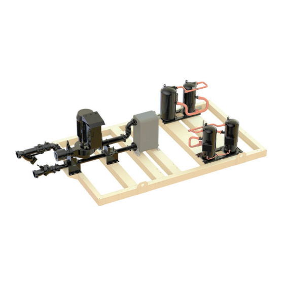
Pump Packages Pump Packages Figure 43: Typical Pump Package Layout Optional Brazed -Plate Controllers Evaporator Vertical Pump Evap In Pressure Gauge/ Vent Ports Shut-off - Suction Butterfly Valve Guide “Y”Type Inlet Strainer Chilled Water Inlet NOTE: Some refrigerant piping Chilled removed for clarity of graphic. - Page 42 • Storage tanks - vertical, insulated, (150, 300, 600, Pump performance curves are generated by Daikin Tools for 1000 gallon sizes) with optional immersion heater, field the specific criteria of the installation. Contact a Daikin Applied installed. Dual Pump Package with Storage Tank representative for this information.
- Page 43 Daikin Applied offers a variable chilled water flow system, completely self-contained within the pump package, by simply ordering the optional pump VFD and no...
- Page 44 Pump Packages out into the system is a popular recommendation) although physically re-positioning the sensor at commissioning stage can be a costly exercise. With Sensorless pump control it is possible to replicate the moving of a sensor by adjusting the head setting ‘Hmin’.
-
Page 45: Dimensions And Weights - Pump Package Units
Dimensions and Weights - Pump Package Units Dimensions and Weights - Pump Package Units Figure 47: Representative Refrigerant System Schematic www.DaikinApplied.com IOM 1207-6 • TRAILBLAZER MODEL AGZ CHILLERS ®... - Page 46 Dimensions and Weights - Pump Package Units Figure 48: 4 Fan Units (AGZ030E-AGZ035E) with Dual Pumps IOM 1207-6 • TRAILBLAZER MODEL AGZ CHILLERS www.DaikinApplied.com ®...
- Page 47 Dimensions and Weights - Pump Package Units Figure 49: 4 Fan Units (AGZ040E-AGZ070E) with Dual Pumps www.DaikinApplied.com IOM 1207-6 • TRAILBLAZER MODEL AGZ CHILLERS ®...
- Page 48 Dimensions and Weights - Pump Package Units Figure 50: 6 Fan Units (AGZ075E-AGZ100E) with Dual Pumps IOM 1207-6 • TRAILBLAZER MODEL AGZ CHILLERS www.DaikinApplied.com ®...
- Page 49 Dimensions and Weights - Pump Package Units Figure 51: 6 Fan Units (AGZ075E-AGZ100E) with Single Pump www.DaikinApplied.com IOM 1207-6 • TRAILBLAZER MODEL AGZ CHILLERS ®...
- Page 50 Dimensions and Weights - Pump Package Units Figure 52: 8 Fan Units (AGZ0110E-AGZ130E) with Dual Pumps IOM 1207-6 • TRAILBLAZER MODEL AGZ CHILLERS www.DaikinApplied.com ®...
- Page 51 Dimensions and Weights - Pump Package Units Figure 53: 8 Fan Units (AGZ0110E-AGZ130E) with Single Pump www.DaikinApplied.com IOM 1207-6 • TRAILBLAZER MODEL AGZ CHILLERS ®...
- Page 52 Dimensions and Weights - Pump Package Units Figure 54: 10 Fan Units (AGZ0140E-AGZ180E) with Dual Pumps IOM 1207-6 • TRAILBLAZER MODEL AGZ CHILLERS www.DaikinApplied.com ®...
- Page 53 Dimensions and Weights - Pump Package Units Figure 55: 10 Fan Units (AGZ0140E-AGZ180E) with Single Pump www.DaikinApplied.com IOM 1207-6 • TRAILBLAZER MODEL AGZ CHILLERS ®...
- Page 54 Dimensions and Weights - Pump Package Units Figure 56: 12 Fan Units (AGZ0191E-AGZ211E) with Dual Pumps IOM 1207-6 • TRAILBLAZER MODEL AGZ CHILLERS www.DaikinApplied.com ®...
- Page 55 Dimensions and Weights - Pump Package Units Figure 57: 12 Fan Units (AGZ0191E-AGZ211E) with Single Pump www.DaikinApplied.com IOM 1207-6 • TRAILBLAZER MODEL AGZ CHILLERS ®...
- Page 56 Dimensions and Weights - Pump Package Units Figure 58: 14 Fan Units (AGZ226E-AGZ241E) with Dual Pumps IOM 1207-6 • TRAILBLAZER MODEL AGZ CHILLERS www.DaikinApplied.com ®...
- Page 57 Dimensions and Weights - Pump Package Units Figure 59: 14 Fan Units (AGZ226E-AGZ241E) with Single Pump www.DaikinApplied.com IOM 1207-6 • TRAILBLAZER MODEL AGZ CHILLERS ®...
-
Page 58: Refrigerant Charge
Refrigerant Charge Refrigerant Charge Table 10: Refrigerant Charge - Pump Package with Microchannel Coils Microchannel Coil Unit Operating Charge - lbs (kg) Unit Replaceable Core Filter Drier Sealed Filter Drier Models Circuit 1 Circuit 2 Circuit 1 Circuit 2 030E 17 (7.7) 17 (7.7) 15 (16.8) -
Page 59: Isolator Information
ELASTOMERIC PAD mounted at the defined mounting point locations along the full rail length. Figure 61: Rubber-in-Shear (RIS) Isolator Contact a Daikin Applied sales representative for isolator information related to units with other fin materials. www.DaikinApplied.com IOM 1207-6 • TRAILBLAZER MODEL AGZ CHILLERS ®... - Page 60 Isolator Information Table 11: Spring Isolator Kits Table 12: RIS Isolator Kits Pump Package/ Remote Pump Package/ Remote AGZ-E AGZ-E Microchannel Evaporator Microchannel Evaporator Model Model Single Pump Dual Pump Microchannel Single Pumps Dual Pumps Microchannel 332320104 332320104 332320102 332325101 332325101 332325129 332320104...
- Page 61 Isolator Information Table 13: Isolator Information - Remote Condensing Units with Microchannel Coils Rubber-In-Shear (RIS) Mounts - RP-3 & RP-4 Models Spring Isolator Mounts - CP-2 Models AGZ-E Coil Model Type Gray Gray Green Green Black Black Green Purple Gray Gray Green Green Black...
- Page 62 Isolator Information Table 14: Isolator Information - Single Pump Packages with Microchannel Rubber-In-Shear (RIS) Mounts - RP- 4 Models Spring Isolator Mounts - CP-2 Models AGZ-E Model Brown Brown Brown Brown Green Green Purple Purple Brown Brown Brown Brown Green Green Purple Purple...
- Page 63 Isolator Information Table 15: Isolator Information - Dual Pump Packages with Microchannel Rubber-In-Shear (RIS) Mounts - RP- 4 Models Spring Isolator Mounts - CP-2 Models AGZ-E Model Brown Brown Brown Brown Green Green Purple Purple Brown Brown Brown Brown Green Green Purple Purple...
-
Page 64: Electrical Data
Electrical Data Electrical Data Electrical Connection DANGER Disconnect, lockout and tag all power to the unit before Trailblazer units can be ordered with either standard multi- ® servicing condenser fan motors or compressors. Failure to do point power or optional single point power connections and so can cause bodily injury or death. - Page 65 Electrical Data Figure 62: Typical Field Wiring Diagram (Single-Point Connection) FIELD WIRING DIAGRAM WITH MICROTECH CONTROLLER PANEL DISCONNECT SWITCH CIRCUIT BREAKER (BY OTHERS) POWER BLOCK 3 PHASE POWER COMPRESSOR(S) SOURCE AND FAN MOTORS EARTH GROUND 120 VAC CHWR1 DISCONNECT PUMP NO.1 RELAY (BY OTHERS) CONTROL (BY OTHERS)
- Page 66 Electrical Data Figure 63: Typical Field Wiring Diagram (Multi-Point Connection) FIELD WIRING DIAGRAM WITH MICROTECH CONTROLLER PANEL DISCONNECT SWITCH CIRCUIT BREAKER 1 (BY OTHERS) POWER BLOCK 3 PHASE TO CIRCUIT 1 POWER COMPRESSOR(S) SOURCE AND FAN MOTORS Note: Separate grounding is required if fed from different transformers.
-
Page 67: Unit Controller Operation
Unit Controller Operation Unit Controller Operation General Description The MicroTech III controller’s design not only permits Security protection prevents unauthorized changing of the ® the chiller to run more efficiently, but also can simplify setpoints and control parameters. troubleshooting if a system failure occurs. Every MicroTech ®... - Page 68 Unit Controller Operation Controller Inputs and Outputs Table 23: Digital Inputs Description Signal Off Signal On Main Controller Circuit 1 Switch Circuit Disable Circuit Enable Circuit 1 MHP Switch Fault No fault Table 18: Analog Inputs Circuit 1 Motor Fault No fault Description Signal Type...
- Page 69 Unit Controller Operation EXV Module 1 and 2 These modules will be used only when the expansion valve type is electronic. Table 28: Digital Outputs Description Output Off Output On Circuit 1 or 2 Fan Fan(s) Off Fan(s) On Output 5 Table 29: Stepper Motor Output Description M1+, M1-...
- Page 70 Unit Controller Operation Table 32: AGZ-E Models with 2 VFDs per Circuit Number of Fans Physical Output Descr . Output Speed 1 UC X5 Fan 11 Fan 11/13 Fan 11/13 Fan 11/13 Fan 11/13 Speed 2 UC X2 Fan 12/13 Fan 12/14 Fan 12/14 Fan 12/14/15/16 Fan 12/14/15/16...
- Page 71 Unit Controller Operation Set Points Set points are initially set to the values in the Default column, order to apply a change. If an option is not included on the unit, and can be adjusted to any value in the Range column. the respective set point may not be visible.
- Page 72 Unit Controller Operation Table 35: Unit Level Set Point Defaults and Ranges (continued) Thursday Duration 12 hrs 0 to 24 hrs Friday Start Time 22:00 00:00 to 23:00 Friday Duration 12 hrs 0 to 24 hrs Saturday Start Time 22:00 00:00 to 23:00 Saturday Duration 12 hrs...
- Page 73 Unit Controller Operation Table 40: Design Conditions Description Default Range Design Evaporator EWT 0°C (32°F) -9.5°C to 28.34°C (14.9°F to 83°F) Design Evaporator LWT 0°C (32°F) -9.5°C to 18.34°C (14.9°F to 65°F) Design Evaporator Water Flow 0 lph (0 gpm) 0 to 908399 lph (0 to 4000 gpm) Design Evaporator Approach Circuit 1/2 0°C (0°F)
- Page 74 Unit Controller Operation Table 43: Communication Configuration Description Default Range Controller IP DHCP Off, On Controller IP Network Address 192.168.001.042 000.000.000.000 to 255.255.255.255 Controller IP Network Mask 255.255.255.000 000.000.000.000 to 255.255.255.255 Controller IP Network Gateway 192.168.001.001 000.000.000.000 to 255.255.255.255 Lon Module Maximum Send Time 0 seconds 0 to 6553.4 seconds Lon Module Minimum Send Time...
- Page 75 Unit Controller Operation Circuit Level Set Points The settings in this section all exist for each individual circuit. Table 44: Set Points for Individual Circuits Description Default Range Mode/Enabling Circuit mode Enable Disable, Enable, Test Compressor 1 Enable Auto Auto, Off Compressor 2 Enable Auto Auto, Off...
- Page 76 Unit Controller Operation Dynamic Set Point Ranges and Defaults Special Set Point Operation Some settings have different ranges of adjustment based EXV settings are only visible if the unit is configured with on other parameters and unit configuration. The condenser electronic expansion valves.
- Page 77 Unit Controller Operation Table 49: Configuration Group 4 Description Default Range Condenser Target - 100% Circuit Capacity 37.78°C(100 °F) 35 to 46.11°C (95 to 115°F) Condenser Target - 67% Circuit Capacity 37.78°C(100 °F) 35 to 40.56°C (95 to 105°F) Condenser Target - 33% Circuit Capacity 26.67°C (80°F) 23.89 to 29.44°C (75 to 85°F) Fan Stage Up Deadband 1...
-
Page 78: Sequence Of Operation
Sequence of Operation Sequence of Operation Figure 65: Unit Sequence of Operation - Cool Mode Unit power up Unit in O state The chiller may be disabled via the unit switch, the remote switch, the keypad enable setting, or the BAS network. In addition, the chiller will be disabled if all circuits are disabled, or if there is a unit alarm. - Page 79 Sequence of Operation Figure 66: Unit Sequence of Operation - Cool Mode (continue) Keep pump output on while chiller is enabled and either running or ready to run. The chiller is now ready to start if enough load is present. If the LWT is not higher than the start up temperature, the unit status will be Auto:Wait for load.
- Page 80 Sequence of Operation Figure 67: Unit Sequence of Operation - Cool Mode (continued) Maintain unit capacity. The unit capacity can be decreasedif the LWTis below the stage down Can less circuits handle temperature. the load? Has the stage down A minimum time must pass between decreases in unit capacity. time delay expired? Compressors will shut o as needed in the order determined by sequencing logic.
- Page 81 Sequence of Operation Figure 68: Unit Sequence of Operation - Ice Mode Unit power up Unit in O state The chiller may be disabled via the unit switch, the remote switch, the keypad enable setting, or the BAS network. In addition, the chiller will be disabled if all circuits are disabled, or if there is a unit alarm.
- Page 82 Sequence of Operation Figure 69: Unit Sequence of Operation - Ice Mode (continued) Pump output remains on while chiller is enabled. If the chiller is waiting on the motor protection delay after powering up, the unit Is Motor Protection status will be O :Motor Protection Delay. delay active? Keep pump output on while chiller is enabled and either...
- Page 83 Sequence of Operation Figure 70: Unit Sequence of Operation - Ice Mode (continued) If the second circuit is not running, it will be started now. The unit will try to keep the load balanced between circuits as the unit capacity is increased. Increase unit capacity.
- Page 84 Sequence of Operation Figure 71: Circuit Sequence of Operation Unit power up When the circuit is in the O state the EXV is in the closed position, compressors are Circuit is in O state o , solenoid valves are closed, and all condenser fans are o . The circuit must be enabled before it can run.
-
Page 85: Unit Functions
Unit Functions Unit Functions The calculations in this section are used in unit level control means the flow that is needed for a 5.56°C (10°F) delta T at full logic or in control logic across all circuits. unit capacity. Evaporator Delta T Table 50: Minimum Flows and Corresponding Maximum Effective Full Capacity Delta T with Variable Flow The evaporator water delta T is calculated as entering water... - Page 86 Unit Functions the Control Band: Table 51: Unit Mode Settings • Start Up Temperature = Stage Up Temperature + Start Up Control Available Delta set point Source Set Mode Input Modes Set Unit Mode Request Point Point • Shutdown Temperature = Stage Down Temperature – Shutdown Delta set point Cool Cool...
- Page 87 Unit Functions T1 - Off to Auto the Low OAT Lockout set point is configurable if the chiller has condenser fan VFD’s. In that case, there are three options: All of the following are required: • Lockout and Stop – chiller will shut down and lockout •...
- Page 88 Unit Functions Unit Status Evaporator Pump Control The displayed unit status should be determined by the For control of the evaporator pumps, three evaporator pump conditions in the following table: control states should be used: Status Conditions Off - No pump on. Auto Unit State = Auto Start –...
- Page 89 Unit Functions LWT Target Freeze Protection To protect the evaporator from freezing, the evaporator pump The LWT Target varies based on settings and inputs. will start if all of the following are true: The base LWT Target is selected as follows: •...
- Page 90 Unit Functions Additional compressors can be started when Evaporator LWT • if run hours are equal, the lowest numbered one will be is higher than the Stage Up Temperature and the Stage Up next to start Delay is not active. If the circuits have an unequal number of compressors running, the next compressor to start will be on the circuit with the least When multiple compressors are running, one should shut down...
- Page 91 Unit Functions Table 53: Stage Limits - Six Compressors When the limit is active, the unit is allowed to run all but one compressor. So it will inhibit the unit from loading if all but one Demand Limit Signal Demand Limit Range Stage compressor is on, and it will shut down a compressor if all (mA)
- Page 92 Unit Functions Compressor Starting changed to use the 110 second delay discussed above only when the chiller is performing the RapidRestore operation. During normal operation, chiller controls will limit compressor starts by enforcing the circuit configuration timers listed in Fast Loading Table 44 on page 75 These timers are further discussed Fast loading will be performed when the following conditions...
-
Page 93: Circuit Functions
Circuit Functions Circuit Functions Calculations Circuit States The circuit will always be in one of four states: Refrigerant Saturated Temperature Off – Circuit is not running Refrigerant saturated temperature shall be calculated from the Preopen – Circuit is preparing to start pressure sensor readings for each circuit. - Page 94 Circuit Functions Circuit Status T6 – Preopen to Off Any of the following are required: The displayed circuit status should be determined by the conditions in the following table: If more than one status • Unit State = Off is enabled at the same time, the highest numbered status •...
- Page 95 Circuit Functions Cycle Timers Table 57: 2 Fans per Circuit - Without Fan VFD Circuit 1 A minimum time between starts of the compressor and a Stage minimum time between shutdown and start of the compressor Description Output Fans shall be enforced. The time values are determined by the Fan Output 1 UC DO3 Fan 11 On On...
- Page 96 Circuit Functions Table 60: 3 Fans per Circuit - With 1 Fan VFD per Circuit Table 62: 4 Fans per Circuit - Without Fan VFD Circuit 1 Circuit 1 Stage Stage Description Output Fans Description Output Fans Fan Output 1 UC DO3 Fan 11 On On On On Speed Signal 1 UC X5...
- Page 97 Circuit Functions Figure 75: 5 Fans per Circuit - Unit Numbering Schematic Table 67: 5 Fans per Circuit - With 2 Fan VFDs per Circuit Circuit 1 5-Fan Locations and Numbering Stage Description Output Fans Speed Signal 1 UC X5 Fan 11/13 On On On Fan 15 Fan 24...
- Page 98 Circuit Functions Table 69: 6 Fans per Circuit - With 1 Fan VFD per Circuit Circuit 2 Circuit 1 Stage Description Output Fans Stage Description Output Fans Fan Output 1 UC DO7 Fan 21/23 On On On On On Speed Signal 1 UC X5 Fan 11/13 On On On On On Fan Output 2...
- Page 99 Circuit Functions Condenser Target a condenser stage, and the saturated condenser temperature is not dropping, then a condenser stage will The condenser target is selected based on circuit capacity be added immediately. using the condenser target set points. There are set points In addition, if the circuit has 4 fans, or it has 6 fans and no that establish the condenser target for 33%, 50%, 67%, and fan VFD’s, then the first condenser stage may be skipped at...
- Page 100 Circuit Functions EXV Control other than 0vdc (meaning the connected fans should run), but any time both VFD’s are to be running the speed signals will be the same (there is no independent speed control on the two Control States VFD’s within a circuit).
- Page 101 Circuit Functions Position Commands additional 10%. This addition to the maximum position should be reset when the EXV is no longer in the Superheat Control In order to improve the reliability of the EXV positioning, the state, or a compressor on the circuit stages. position commands that are issued to the stepper driver are limited in two ways: Manual Control...
-
Page 102: Alarms
Alarms Alarms Situations may arise that require some action from the chiller always a manual reset alarm. or that should be logged for future reference. Alarms are Evaporator Water Freeze Protect classified in the following sections as Faults, Problems, or Warnings. - Page 103 Alarms EXV Module 2 Comm Failure Evaporator EWT Sensor Fault Trigger: Expansion Valve Type = Electronic and Trigger: Sensor shorted or open for longer than one second communication with the I/O extension module has failed. Action Taken: None. Action Taken: Rapid stop of circuit 2 . Reset: Auto clear when the sensor is back in range.
- Page 104 Alarms The alarm also requires Evaporator Configuration = Remote running. and Condenser Type = Microchannel to trigger. Reset: This alarm can be cleared manually via the controller Action Taken: Rapid stop circuit. HMI or BAS command if either of the following are true for at least five seconds: Reset: This alarm can be cleared manually via the controller keypad if the MHP switch input is closed.
- Page 105 Alarms Event Log This event is triggered if all of the following are true: • circuit state = Run An Event Log similar to the Alarm Log stores the last 50 • evaporator pressure <= Low Evaporator Pressure - Hold event occurrences.
-
Page 106: Using The Controller
Using the Controller Using the Controller Compressor Communications short cycling. Once locked out the compressor, a power cycle or Modbus reset command will be required to clear the lockout. The CoreSense™ compressor communication module Code 4 – Scroll High Temperature: The module will flash on model sizes 075-241 provides advanced diagnostics, the red Alert LED four times indicating the over-temperature protection, and communications that enhance compressor... - Page 107 Using the Controller Figure 79: Schematic of Unit Controller The keypad/display consists of a 5-line by 22-character include changeable data fields (setpoints). display, three buttons (keys) and a “push and roll” navigation When the cursor is on a line the highlights will look like this: wheel.
- Page 108 O = Operator level Enter PW **** T = Technician/Manager level D = Daikin Applied factory service technician level Entering an invalid password has the same effect as not entering a password. Screen navigational links: Once a valid password has been entered, the controller •...
- Page 109 Using the Controller Figure 84: Controller Keypad Sample Navigation www.DaikinApplied.com IOM 1207-6 • TRAILBLAZER MODEL AGZ CHILLERS ®...
-
Page 110: Fan Vfd Controller
Fan VFD Controller Fan VFD Controller VFD Interface The VFD controller is located in the lower left-hand corner of the unit control panel. It is used to view data including fault and alarm information. No operator intervention on this control is required for normal unit operation. - Page 111 Fan VFD Controller Figure 85: LCD Display Table 76: Display Data Name Display Content MODE Displayed when in Mode Selection. MONITR Displayed when in Monitor Mode. Operation Mode VERIFY Indicates the Verify Menu Menus PRMSET Displayed when in Parameter Setting Mode. A.TUNE Displayed during Auto-Tuning.
- Page 112 Fan VFD Controller Table 77: Alarm Content State Content Illuminated When the drive detects an alarm or error When an alarm occurs Flashing When an oPE is detected When a fault or error occurs during Auto-Tuning Normal operation (no fault or alarm) Table 78: LO/RE LED and RUN LED Indictors Flashing Flashing Quickly...
- Page 113 Fan VFD Controller Table 79: Types of Alarms, Faults, and Errors Type Drive Response When the drive detects a fault: • The digital operator displays text indicating the specific fault and the ALM indicator LED remains lit until the fault is reset. Faults •...
- Page 114 Fan VFD Controller Optional BAS Interface Inverter Output to the Motor The AGZ chiller controller is configured for stand-alone WARNING operation or integration with BAS through an optional Avoid swapping any 2 of the 3 motor lead connections which will communication module.
-
Page 115: Pump Vfd Controller
Pump VFD Controller Pump VFD Controller Pump Start Control (MicroTech III) ® Figure 86: Graphical Local Control Panel (GLCP) The standard arrangement is for the MicroTech III unit ® (a) Status Line controller pump output signal to automatically start and stop the pump(s). - Page 116 Pump VFD Controller Figure 87: Status Display II Three different readouts can be chosen by pressing the [Status] key repeatedly. Normal display is shown in Figure Quick Menu Used for programming only. Main Menu Used for programming all parameters. Alarm Log Displays an Alarm list of the ten latest alarms (numbered A1-A10).
- Page 117 Pump VFD Controller Pump Control Keys corrective measures is below in the section titled Warning/Fault Messages. Operation Control Keys for local control are found at the bottom of the control panel. The key in use will have an LED Resetting Alarms illuminated above it.
- Page 118 The speed has been limited by range in par. 4-11 Motor Speed Low Limit [RPM] and par. 4-13 Motor Speed High Limit [RPM]. ALARM 50 - AMA calibration failed Contact Daikin Applied service. IOM 1207-6 • TRAILBLAZER MODEL AGZ CHILLERS www.DaikinApplied.com...
-
Page 119: Bas Integration Of Pumps
Technical Response Center (TRC). NOTE: AGZ-E chiller VFD controllers support only BACnet MS/TP, LONWORKS, and Modbus communications. Daikin Applied does not support other protocol options that may be offered by the VFD manufacturer. Table 82: BACnet MS/TP Network Configuration Parameters Parameter Setting for BACnet;... - Page 120 BAS Integration of Pumps Configuring the VFD Control for Light Emitting Diodes (LEDs) LON-WORKS Communication Two LEDs indicate communication activity and status of the LonWorks Option Card. These indicators can be seen when This following section assumes you are using a LONWORKS the LonWorks Option Card is connected to the VFD pump Option Card in conjunction with the AGZ-E pump package controller.
- Page 121 BAS Integration of Pumps Table 83: LONWORKS Network Parameters Parameter Value (Range)/Definition Default Value Option A [3]/During initial pow er-up, the frequency converter automatically 8-02 Control Source sets this parameter to Option A [3] if it detects a valid fieldbus option FC Port [1] installed in slot A Variable/This item w ill be blank if the...
- Page 122 BAS Integration of Pumps Configuring the VFD Controller for Table 85: Modbus Network Parameters Parameter Value (Range)/Definition Default Value Modbus Communication 8-02 Control FC Port [1]/ On-board RS-485 port FC Port [1] Source The VFD controller (frequency controller) is a native Modbus Modbus RTU [2]/The protocol device.
-
Page 123: Startup And Shutdown Procedures
Complete the pre-start checklist at the front of retaining clips are installed. this manual and return to Daikin Applied prior to startup date. 3. Put System Switch (S1) to the Emergency Stop position. See the pre-startup section for the pump package on... - Page 124 • Complete the “Equipment Warranty Registration Form,” found at the end of this manual, within 10 days of start- IMPORTANT: Flow switch up in order to comply with the terms of Daikin Limited MUST be calibrated before Product Warranty. chiller operation. Failure to...
- Page 125 Startup and Shutdown Procedures Figure 96: Flow Switch Details adapter/sensor connection to 18.5 ft/lbs. Wiring Refer to wiring diagram in the unit control panel. Either AC or DC is used to power the flow switch. The unit controller’s digital input is a DC signal which is supplied through the switch output of the flow switch for flow indication.
- Page 126 Startup and Shutdown Procedures Table 87: Flow Volume Calculation Inside US GPM at the velocities indicated below Pipe Pipe adjustment Default Size Diameter per '+' or '-' 20 cm/sec 30 cm/sec 50 cm/sec 75 cm/sec 100 cm/sec 150 cm/sec 200 cm/sec 250 cm/sec 300cm/sec (inch) (inch) key input...
- Page 127 Startup and Shutdown Procedures Flow below display range: The SP LED will be lit red and the left most LED will be flashing green. For example, if the SP was set to 200 cm/s, the flashing labeled ‘0’ would indicate that the flow was below 180 cm/s.
-
Page 128: Startup And Shutdown Procedures - Pumps
Startup and Shutdown Procedures - Pumps Startup and Shutdown Procedures - Pumps Pre-Startup Setup #2 External Sensor Follow the chiller startup procedure beginning on page 123 Normally a differential pressure sensor. and complete the pre-start checklist for scroll compressor Setup #3 BAS chillers found in the front of this manual as well as the pump commissioning startup form. - Page 129 Startup and Shutdown Procedures - Pumps Removing Temporary Strainer The temporary strainer must be removed following system clean up as follows: After all debris has been removed from the system, or a maximum of 24 running hours, stop the pump and close the pump isolation valves.
-
Page 130: Unit Maintenance
A recommended maintenance schedule is located at efficiency heat transfer from the refrigerant to the airstream. In the end of this section. the unlikely occurrence of a coil leak, contact Daikin Applied to receive a replacement coil module. Compressor... - Page 131 Unit Maintenance be easily damaged (fin edges bent over) if the tool is applied the product must be able to come in contact with the across the fins. salts. These salts may be beneath any soils, grease or dirt; therefore, these barriers must be removed prior to NOTE: Use of a water stream, such as a garden hose, application of this product.
- Page 132 Unit Maintenance Battery Expansion Valve The expansion valve’s function is to keep the evaporator The controller has included with it a battery (BR2032) with supplied with the proper amount of refrigerant to satisfy the a ~2 year life; therefor, it is recommended to include battery load conditions.
- Page 133 Unit Maintenance Table 89: Planned Maintenance Schedule Monthly Annual Operation Weekly (Note 1) (Note 2) General Complete unit log and review (Note 3) Visually inspect unit for loose or damaged components Inspect thermal insulation for integrity Clean and paint as required Electrical Check terminals for tightness, tighten as necessary Clean control panel interior...
- Page 134 • ANSI/ASHRAE safety group A1. Daikin product. POE oil, if ever in contact with PVC/CPVC, will • Always carry and be familiar with SDS information for coat the inside wall of PVC/CPVC pipe causing environmental R-410a.
- Page 135 Unit Maintenance 100 ppm typical). Overcharging of refrigerant will raise the compressor discharge pressure due to filling of the condenser tubes with excess • Evacuate to 500 microns and hold test to insure systems refrigerant. are dry. Control and Alarm Settings Service With R-410A, fractionalization, if due to leaks and recharge has The software that controls the operation of the unit is factory-...
-
Page 136: Troubleshooting Chart
Troubleshooting Chart Troubleshooting Chart PROBLEM POSSIBLE CAUSES POSSIBLE CORRECTIVE STEPS 1. Main or compressor disconnect switch open. 1. Close switch. 2. Fuse blown. circuit breakers open 2. Check electrical circuits and motor windings for shorts or grounds. Investigate for possible overloading. Check for loose or corroded connections. - Page 137 Troubleshooting Chart PROBLEM POSSIBLE CAUSES POSSIBLE CORRECTIVE STEPS 1. Defective capacity control 1. Replace. Compressor Will Not 2. Faulty sensor or wiring 2. Replace. Stage Up 3. Stages not set for application 3. Adjust controller setting for application. 1. Control band not set properly 1.
-
Page 138: Warranty Registration Form (Scroll)
This form must be completely filled out and returned to Daikin Applied (Warranty Department) within ten (10) days of start-up in order to comply with the terms of the Daikin Limited Product Warranty. Complete and mail to: Daikin Applied, Attn: Warranty Department, PO Box 2510, Staunton, VA 20042-2510 Or email to: stn.wty_startup_regi@DaikinApplied.com... - Page 139 Warranty Registration Form (Scroll) PRE START-UP CHECKLIST Pre Start-Up Checklist, All NO checks require an explanation under "Description". Please check YES or NO A. Is the unit free of visible shipping damage, corrosion or paint problems? B. Is unit level and isolators installed? C.
- Page 140 Warranty Registration Form (Scroll) REFRIGERANT PIPING FOR REMOTE EVAPORATOR APPLICATIONS N/A Yes A. Has all field piping been leak tested at 150 psig (690 kPA)? B. Has system been properly evacuated and charged? C. Refrigerant R- Circuit 1 lbs (kg) Circuit 2 lbs.
- Page 141 Warranty Registration Form (Scroll) G. Circuit #2 Refrigerant Temperatures: Saturated Evaporator Temperature …………………… °F (°C) °F (°C) Suction Line Temperature ………………………………. °F (°C) °F (°C) Suction Superheat ……………………………………..°F (°C) °F (°C) Saturated Condenser Temperature …………………… °F (°C) Liquid Line Temperature ……………………………………………………………...
- Page 142 Address: City/State/Zip Code: Telephone: Modem Number: Signature: Date: Contractor's Signature RETURN COMPLETED FORM TO: DAIKIN, WARRANTY DEPT ., PO BOX 2510, STAUNTON, VA 24402 SF-20001 AGZ/AMZ Start-Up 8/2020 5 of 8 www.DaikinApplied.com IOM 1207-6 • TRAILBLAZER MODEL AGZ CHILLERS www.DaikinApplied.com...
- Page 143 Warranty Registration Form (Scroll) IVS SENSORLESS PUMP COMMISSIONING CHECK SHEET FOR PUMP PACKAGE UNITS ONLY Project Name: Building Address: Contractor Name: Site Contact Tel. #: Site Contact Name: Site Contact #: Your Name: Your Company: Your Name: Pump Tag #: Pump Model: Pump Tag #: Sales Order #:...
- Page 144 Warranty Registration Form (Scroll) (CONT'D) SECTION 2- EXTERNAL SENSOR STARTUP PROCEDURE: 6. Change parameter 6-23 to match the high end of current signal from the sensor (eg: if your sensor provides a 4-20mA signal, enter 20). Go to step 7. 7.
- Page 145 www.DaikinApplied.com IOM 1207-6 • TRAILBLAZER MODEL AGZ CHILLERS ®...
- Page 146 IOM 1207-6 • TRAILBLAZER MODEL AGZ CHILLERS www.DaikinApplied.com ®...
- Page 147 (collectively “Owner”) that Company, at it’s option, will repair or replace defective parts in the event any product manufactured by Company, including products sold under the brand name Daikin and used in the United States or Canada, proves defective in material or workmanship within twelve (12) months from initial startup or eighteen (18) months from the date shipped by Company, whichever occurs first.
- Page 148 Now that you have made an investment in modern, efficient Daikin Applied equipment, its care should be a high priority. For training information on all Daikin Applied HVAC products, please visit us at www.DaikinApplied.com and click on Training, or call 540-248-9646 and ask for the Training Department.
Need help?
Do you have a question about the Trailblazer AGZ030E-070E and is the answer not in the manual?
Questions and answers