Table of Contents
Advertisement
Quick Links
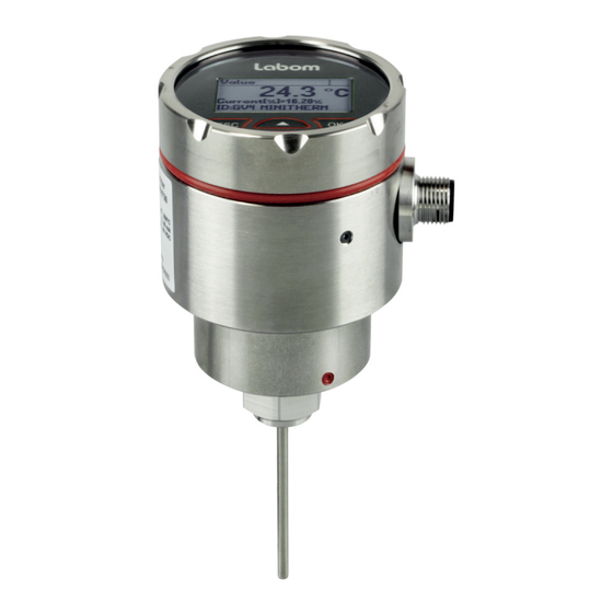
Temperature transmitter MiniTherm
Type series GV4730
Operating Instructions
1 General Information....................................................................................................... 2
1.1 General Safety Notes .............................................................................................. 2
1.2 Intended Use ........................................................................................................... 2
1.3 Conformity with EU Regulations .............................................................................. 2
2 Transportation and Storage .......................................................................................... 2
3 Installation and Commissioning .................................................................................. 2
3.1 Mechanical Installation ............................................................................................ 2
3.2 Mount / Dismount Display ....................................................................................... 3
3.3 Electrical Connection .............................................................................................. 3
3.4 Device orientation ................................................................................................... 3
3.5 Adjustment of the Display Contrast ......................................................................... 4
4 Operation ........................................................................................................................ 4
4.1 Maintenance / Service ............................................................................................. 4
5 Disassembly ................................................................................................................... 4
6 User Manual ................................................................................................................... 5
6.1 Basics of the Operating Concept ............................................................................. 5
6.2 Display Mode / Measured Value Display ................................................................. 6
6.3 Menue Mode / Operating Menue ............................................................................. 9
6.4 The Menue Tree .................................................................................................... 12
LABOM Mess- und Regeltechnik GmbH Im Gewerbepark 13 27798 Hude Germany
Hotline: +49 4408 804-444 Fax: +49 4408 804-100 e-mail: sales@labom.com www.labom.com
BA_085_2019-05_10.00
Page 1/20
Advertisement
Table of Contents

Related Manuals for Labom MiniTherm GV4730 Series


Summary of Contents for Labom MiniTherm GV4730 Series
-
Page 1: Table Of Contents
6.2 Display Mode / Measured Value Display ..............6 6.3 Menue Mode / Operating Menue ................9 6.4 The Menue Tree ....................12 LABOM Mess- und Regeltechnik GmbH Im Gewerbepark 13 27798 Hude Germany BA_085_2019-05_10.00 Hotline: +49 4408 804-444 Fax: +49 4408 804-100 e-mail: sales@labom.com www.labom.com... -
Page 2: General Information
In addition to this instruction, be sure to observe all statutory requirements, appli- cable standards, the additional technical specifications on the accompanying data sheet (see www.labom.com) as well as the specifications indicated on the type plate. General Safety Notes The installation, set up, service or disassembly of this device must only be done by trained, qualified personnel using suitable equipment and authorized to do so. -
Page 3: Mount / Dismount Display
Mount / Dismount Display In order to dismount the display, turn off the device cover and pull out the display. The three small studs at the outer diameter of the display (all 120°) facilitate removal. The display cable can be disconnected either at the display or at the clamp module. When reconnecting the cable, please take polarity (red lead) into account. -
Page 4: Adjustment Of The Display Contrast
Adjustment of the Display Contrast The display contrast can be adjusted. Press and hold the ESC key and use the arrow keys to adapt the contrast. The setting is saved and the contrast screen closes as soon as the ESC key is released. Operation During operation, take care that the device remains within its intended pressure and tem- perature ranges. -
Page 5: User Manual
User Manual The device can be configured via the display module as well as the HART protocol. The following pages describe operation and configuration of the device using the display mod- ule. An overview of the menue structure can be found on the last page of this document. Basics of the Operating Concept The display module consists of a dot-matrix display with 80x128 pixels as well as a... -
Page 6: Display Mode / Measured Value Display
The icon for the device status (see 6.2.3) is displayed in each operating mode. The con- tents of the header and the data area depend on the operating mode: Display of measured value Header: Icon description, if applicable. Otherwise "Value" ... - Page 7 The sequence of the screens with device data is as follows: Min/Max values (measurement) ----- Measured value display (starting point) --- Temperature measurement (senor type) Current output (characteristic curve, limits, measuring range) HART data (address, tag, descriptor) ...
- Page 8 6.2.4 Display layouts You can configure the layout of the measured value display as well as the displayed infor- mation individually. There are four different layouts available: Designation Layout Description Example Four values Under the main value, three additional values are shown. The 4th value can use the entire display width.
-
Page 9: Menue Mode / Operating Menue
Menue Mode / Operating Menue Press OK in the measured value display to go to the operating menue. Then the main menue appears in the display. In the operating menue you can navigate in the menues by using the arrow buttons. The selected menue item is indicated by triangles on the left and right. - Page 10 6.3.1 Displaying and entering parameters When entering parameters, either numerical inputs or a selection lists with fixed options is available. In general, the actual selection will be displayed first (view mode). Press OK to switch to edit mode to change the parameter. After this is done, the display will then switch back to view mode so that you can check the new setting.
- Page 11 After selecting a menue item for numerical entry (e.g. Upper range value), at first the value is displayed only. The numeric value itself is shown in square brackets and its unit behind it or in the lower right area. Unused leading digits are marked with bottom lines. You need to press OK again to enter the edit mode.
-
Page 12: The Menue Tree
The Menue Tree In the following, the display and adjustment options are described by their position in the menue tree. An overview of the menue tree can be found on the last page of this docu- ment. 6.4.1 Main menue The main menue has the following entries: Menue entry Description... - Page 13 6.4.3 "Adjustment" menue The following functions are available for the temperature adjustment: Menue entry Description Lower adjust. Offset correction with applied reference temperature Upper adjust. Span correction with applied reference temperature Table 8: "Adjustment" menue 6.4.3.1 Upper and lower adjustment The lower adjustment results in an offset of the characteristic curve.
- Page 14 Proceed as follows (example for 4 mA): Select function "Current adjust." –> "Adjust. 4 mA" Use "OK" to activate constant current mode (4 mA). CAUTION! The output current value now no longer corresponds with the measured value! This is indicated by the icon "Function check"...
- Page 15 6.4.4.2 Submenue "Screen mode" In the "Screen mode" submenue, you configure the representation of the measured values and additional information on the display. With the menue item “Screen layout” you configure the information that is displayed and its layout. Up to four values can be displayed at the same time. In the additional menue en- tries "1st value"...
- Page 16 6.4.6 Menue "Diagnosis" In this menue you can view and configure various diagnostic information. The following diagnostic functions are available: Menue entry Description Operating hours Display of operating hour counter Min/Max values Displaying and resetting the min/max values Last error Display and reset of the last critical error Table 12: "Diagnosis"...
- Page 17 6.4.8.1 HART address This address corresponds with the short address which is used for the HART- Communication. It can be set within a range of 0 to 63. Please note, that setting the short address between 1 and 63 will not automatically activate the constant current mode. This must be done under the menue “Current mode”...
- Page 18 BA_085_2019-05_10.00 Temperature transmitter MiniTherm Page 18/20...
- Page 19 BA_085_2019-05_10.00 Temperature transmitter MiniTherm Page 19/20...
- Page 20 6.4.10 Overview with menue tree and device functions BA_085_2019-05_10.00 Temperature transmitter MiniTherm Page 20/20...
Need help?
Do you have a question about the MiniTherm GV4730 Series and is the answer not in the manual?
Questions and answers