Table of Contents
Advertisement
Quick Links
Operation - Repair
RS Gun, Cutter
For use with polyester resin and gel-coat.
For professional use only.
Important Safety Instructions
Read all warnings and instructions in this
manual. Save these instructions.
See page 3 for model information, including maxi-
mum working pressure.
Patents Pending
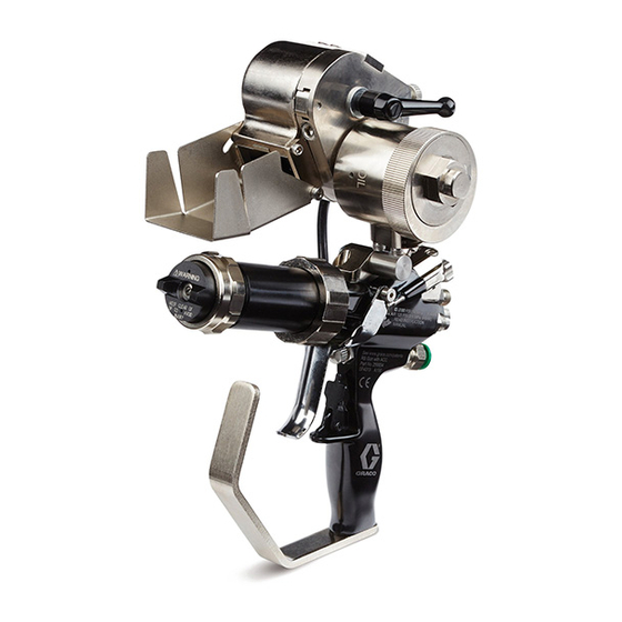
External Mix Chop Gun with Cutter shown
3A0232E
ENG
258970_3A0232_1a
II 2 G c T6
Advertisement
Table of Contents

Related Manuals for Graco 258853


Summary of Contents for Graco 258853
- Page 1 Operation - Repair RS Gun, Cutter 3A0232E For use with polyester resin and gel-coat. For professional use only. Important Safety Instructions Read all warnings and instructions in this manual. Save these instructions. See page 3 for model information, including maxi- mum working pressure.
-
Page 2: Table Of Contents
Blower Air Adjustment ....21 Graco Information ......54 Pressure Relief Procedure . -
Page 3: Models
Pressure Range Temperature Model Description psi (MPa, bar) psi (MPa, bar) psi (MPa, bar) °F (°C) Internal Mix 0-125 258853 2000 (14, 138) 2000 (14, 138) 100 (38) Gel Gun (0-0.86, 0-8.6) Internal Mix 0-125 258854 Chop Gun, 2000 (14, 138) -
Page 4: Warnings
Warnings Warnings The following warnings are for the setup, use, grounding, maintenance, and repair of this equipment. The exclama- tion point symbol alerts you to a general warning and the hazard symbols refer to procedure-specific risks. When these symbols appear in the body of this manual, refer back to these Warnings. Product-specific hazard symbols and warnings not covered in this section may appear throughout the body of this manual where applicable. - Page 5 Warnings WARNING TOXIC FLUID OR FUMES HAZARD Toxic fluids or fumes can cause serious injury or death if splashed in the eyes or on skin, inhaled, or swallowed. • Read MSDSs to know the specific hazards of the fluids you are using. •...
-
Page 6: Important Two-Component Information
Important Two-Component Information Important Two-Component Information Material Self-ignition Some materials may become self-igniting if applied too thickly. Read material manufacturer’s warnings and material MSDS. Keep Components A and B Separate Cross-contamination can result in cured material in fluid lines which could cause serious injury or damage equipment. -
Page 7: Important Methyl Ethyl Ketone Peroxide (Mekp) Safety Information
Use only original equipment or equivalent parts ing and disposal. from Graco in the catalyst system (i.e.: hoses, fittings, Workers must be thoroughly informed of the hazards etc.) because a hazardous chemical reaction may that may result from improper handling of MEKP, espe- result between substituted parts and MEKP. - Page 8 MSDS to know specific hazards and precautions. (Graco recom- mends that clean-up solvents be nonflammable.) NOTE: Graco recommends that you consult OSHA Sec- tions 1910.94, 1910.106, 1910.107 and NFPA No. 33, Chapter 16,17, and NFPA No. 91 for further guidance.
- Page 9 Important Methyl Ethyl Ketone Peroxide (MEKP) Safety Information 3A0232E...
-
Page 10: Component Identification
Component Identification Component Identification External Mix Gel Gun, 258840 258840_3A0232_1g Key: Trigger Clamp Assembly Spray Tip Gun Mount Trigger guard Front Head Locking Ring Trigger Air Cap Retaining Ring Trigger lock External Mix Aircap Handle External Mix Front Head Actuator Pin 3A0232E... -
Page 11: Internal Mix Gel Gun, 258853
Component Identification Internal Mix Gel Gun, 258853 NOTE: On internal mix guns, the tip rotates to allow ver- tical or horizontal spray pattern. 258853_3A0232_1h Key: Trigger Clamp Assembly Spray Tip Gun Mount Trigger guard Front Head Locking Ring Trigger Air Cap Retaining Ring... -
Page 12: Internal Mix Chop Gun, 258854
Component Identification Internal Mix Chop Gun, 258854 NOTE: On internal mix guns, the tip rotates to allow ver- tical or horizontal spray pattern. 258854_3A0232_1h Key: Trigger Clamp Assembly Spray Tip Cutter Mount Trigger guard Front Head Locking Ring Trigger Air Cap Retaining Ring Trigger lock Internal Mix Aircap Handle... -
Page 13: External Mix Chop Gun, 258852
Component Identification External Mix Chop Gun, 258852 258852_3A0232_2g Key: Trigger Clamp Assembly Spray Tip Cutter Mount Trigger guard Front Head Locking Ring Trigger Air Cap Retaining Ring Trigger lock External Mix Aircap Handle External Mix Front Head Actuator Pin 3A0232E... -
Page 14: Cutter, 24E512
Component Identification Cutter, 24E512 258900_3A0232_1j Key: AA Blade Cartridge AG Anvil to Blade Tension AB Cutter Head Assembly Cap Lockdown AC Anvil AH Air Motor AD Anvil Cap AJ Idler Wheel AE Glass Feed AK Motor Lock button AF Anvil to Blade Tension AL Cover (not shown) Adjustment Knob AM Chute (not shown) -
Page 15: Theory Of Operation
NOTE: Grounding wire and clamp assembly 17440-00 Internal Mix is included with Graco FRP proportioner. If using a dif- ferent proportioner that does not come with a ground- The material and catalyst pass through an internal static ing wire and clamp assembly, order 17440-00 or mixer where they mix. -
Page 16: Setup
Setup Setup 1. Before first use, flush the gun. The equipment was 8. For guns with cutters, adjust anvil to blade ten- tested with lightweight oil, which is left in the fluid sion: passages to protect parts. To avoid contaminating a. - Page 17 Setup 258840_3A0232_2g External Mix Internal Mix Chop Internal Mix Gel Fitting Size Atomized Air Air Assist Contain- Plugged 1/4 tube (Catalyst) ment (AAC) Resin Inlet 1/4 NPSM Air Assist Con- Solvent 1/8 NPSM tainment (AAC) Adjustment Knob Air Assist Contain- Chop Air Inlet 3/8 tube ment (AAC)
-
Page 18: Operation
Operation Operation Trigger Clamp Adjustment Procedure High-pressure fluid from gun, hose leaks, or ruptured components will pierce skin. This may look like just a cut, but it is a serious injury that can result in amputa- tion. Get immediate surgical treatment. •... -
Page 19: Trigger Adjustment
Operation Trigger Adjustment 10. While watching the trigger clamp assembly, trigger the gun to verify both sides of the trigger clamp assembly pull away from the gun body at the same time. Good When the trigger is pulled, it moves the trigger clamp assembly resulting in fluid flow from each component. -
Page 20: Cutter Assembly
Operation Cutter Assembly 2. Engage trigger lock. To prevent skin injection, engage the trigger lock before adjusting cutter motor. 3. With the trigger lock engaged, rotate the cutter motor (AJ): clockwise to decrease speed, coun- ter-clockwise to increase speed. See F . -
Page 21: Adjust Anvil To Idler Tension
Operation Adjust Anvil to Idler Tension To adjust the anvil (AC) to idler (AJ) tension, the idler position can be adjusted. 1. Follow Pressure Relief Procedure, page 22. 2. Engage trigger lock. 3. Loosen knob (528) then remove cover (527). See page 42. -
Page 22: Pressure Relief Procedure
Pressure Relief Procedure Pressure Relief Shutdown Procedure Daily 1. Shutdown proportioner. 1. Perform Pressure Relief Procedure. 2. Relieve proportioner pressure. See proportioner 2. Perform Clean Gun Front End procedure, see manual. page 24. 3. Engage gun trigger lock. Long-Term 4. Close the bleed-type master air valve. 5. -
Page 23: Maintenance
Maintenance Maintenance Tools Required Flush Gun The following tools are required to perform regular main- tenance on the gun. • 7/16 in. wrench • 1/2 in. wrench NOTE: • 9/16 in. wrench • Flush before changing colors, before fluid can dry in •... -
Page 24: Clean Gun Front End
Maintenance Clean Gun Front End 5. Apply lube (Part No. 118665) to check valve housing o-rings prior to installing the front head onto the gun. 6. Align front head with check valve and install front head then tighten locking ring (C). 7. -
Page 25: Replace Internal Mix Element
Maintenance Replace Internal Mix Element . 14 See internal mix front head parts list on page 45 for 8. Install check valve (812) and spring (813) into the seat then install cap (806). See F . 15 for orienta- available kits. tion of parts. -
Page 26: Replace External Mix Check Valve And O-Rings
Maintenance Replace External Mix Check Valve and O-Rings . 16 See Front Head Assemblies beginning on page 44 for 10. Install air cap onto head and tighten retaining available kits. ring (710). 1. Perform Pressure Relief Procedure, page 22. NOTICE To prevent distorting the end of the cap (706), do 2. -
Page 27: Adjust Needle Packing
Maintenance Adjust Needle Packing Replace Needle Packing If there is a fluid leak at the rear of the needle assembly, NOTE: The needle packing is the seal (904) inside the the packings can be tightened to stop the leak. needle assembly (105). See pages 34 and 46. 1. -
Page 28: Replace Material Needle Assembly
3. Use 1/2 in. deep well socket to break loose and remove material needle assemblies. 4. Install new material needle assemblies. 4. Add 3-4 drops of air motor oil, Graco part 202659, 5. Ensure needle flats are aligned with one another. into oil hole on air motor. -
Page 29: Anvil Replacement
Maintenance Anvil Replacement 10. Install cover and knob. 11. Adjust Anvil to Blade Cartridge Tension, page 20. Blade Cartridge Replacement If glass is not getting cut properly, verify the tension is correct before replacing the blade cartridge. 1. Follow Pressure Relief Procedure, page 22. 2. -
Page 30: Troubleshooting
Troubleshooting Troubleshooting Problem Cause Solution Gun does not fully Safety lock engaged Disengage safety lock actuate when trig- Trigger clamp pins bent Inspect and replace if necessary gered Cutter air valve stuck Inspect and replace if necessary Overspray on trigger clamp pins Clean and lubricate Needle assembly stuck Check and adjust needle packing tension... - Page 31 Troubleshooting Problem Cause Solution Catalyst pressure Trigger clamp out of phase Adjust trigger clamp, see page 18 dumps on initial trig- Material continues to Foreign object under trigger clamp Clean and replace if necessary spray after trigger is Overspray on trigger clamp pins Clean and lubricate released Actuator pins sticking...
- Page 32 Troubleshooting Problem Cause Solution Material not mixed External mix catalyst tips plugged Clean and replace Atomizing air pressure too low Adjust Static mixer missing Replace Static mixer worn Inspect and replace if necessary Incorrect static mixer Replace if necessary AAC does not func- Air supply to gun is shut off Open air supply tion...
- Page 33 Troubleshooting Problem Cause Solution No solvent No fluid in pressure pot Refill pressure pot Output valve closed Open output valve Check valve stuck closed Increase pressure in pressure pot Material check valve plugged Clean and replace as needed Solvent needle valve closed Open solvent needle valve Solvent check valve stuck closed Ensure the solvent check valve opens freely...
-
Page 34: Parts
Parts Parts External Mix Gel Gun, 258840 258840_3A0232_4g 3A0232E... - Page 35 Parts Part Description 16C279 BODY, gel gun mount Part Description 239663 SWIVEL, straight HANDLE, gun 123909 SCREW, cap, sh 102†‡ 24E428 SEAL, needle, seat (pack of 6) SCREW, set 103‡ RETAINER, seat, needle valve, 24F007 KIT, tool, hex keys, gun resin GC2081 SCREW, set 104†...
-
Page 36: Internal Mix Gel Gun, 258853
Parts Internal Mix Gel Gun, 258853 258853_3A0232_2h 3A0232E... - Page 37 Parts Part Description 237★ RESTRICTOR, catalyst Part Description 238★ 16C108 FITTING, catalyst hose HANDLE, gun 16C279 BODY, gel gun mount 202†‡ 24E428 SEAL, needle, seat (pack of 6) 123909 SCREW, cap, sh 203‡ RETAINER, seat, needle valve, 111316 PACKING, o-ring resin 239663 SWIVEL, straight 204†...
- Page 38 Parts 3A0232E...
-
Page 39: External Mix Chop Gun With Cutter, 258970
Parts External Mix Chop Gun with Cutter, 258970 Ref Part Description 301 258852 GUN, external mix, chop 302 24E512 CUTTER ASSEMBLY Internal Mix Chop Gun with Cutter, 258971 Ref Part Description 401 258854 GUN, internal mix, chop 302 24E512 CUTTER ASSEMBLY 301, 401 External Mix Chop Gun shown 258970_3A0232_8a... -
Page 40: Chop Guns, 258852, 258854
Parts Chop Guns, 258852, 258854 516a 516b 258854_3A0232_2j Internal Mix Chop Gun shown Quantity Part Description 258852 258854 Quantity 510❄ 24E430 O-RING (pack of 6) Part Description 258852 258854 HANDLE, gun 511✿ CLAMP, trigger, top 502†‡ 24E428 SEAL, needle, seat 512✿... - Page 41 Parts † Parts included in catalyst seat kit 24E420. Quantity Part Description 258852 258854 ◆ Parts included in Cutter Adapter Kits. 24E426 HEAD, asm, ext mix, horiz ‡ Parts included in resin seat kit 24E421. 24E442 HEAD, asm, internal mix, chop ✿...
-
Page 42: Cutter Assembly, 24E512
Parts Cutter Assembly, 24E512 NOTICE To prevent undesired operation, do not disassem- ble any part of the air motor (602) except for the air motor muffler as shown in the Air Motor Muffler section on page 49. 258900_3A0232_2j 258900_3A0232_4j 3A0232E... - Page 43 Parts Part Description 16E010 SCREW, adjusting Part Description 636◆ --- WASHER, spring, belleville PLATE, cutter back 104893 PACKING, o ring 602† 24E511 MOTOR, air 15G117 O-RING 117519 O-RING 642◆ 16E227 DEFLECTOR, chute, chopper, rs 111945 SCREW, cap, fl hd 643◆ --- SCREW, shldr, shc 605✿...
-
Page 44: Front Head Assemblies
Parts Front Head Assemblies External Mix Vertical Spray Pattern Front Head, 24E426 External Mix Horizontal Spray Pattern Front Head, 24E427 708a 708a Part Description HEAD, spray, external mix 16C220 RING, locking 703* SEAL, tip, external mix 704*† BALL, sst 705*† SPRING, compression 706* CAP, check valve, external mix... - Page 45 Parts Internal Mix Gel Front Head, 24E442 Internal Mix Chop Front Head, 24G615 NOTICE There is a half-moon pin pressed into the front head (801) behind the diffuser assembly (803). Do not attempt to remove this pin. Removal will result in unde- sired operation.
-
Page 46: Needle Assembly, 24E417
Parts Needle Assembly, 24E417 ti16592a Beveled edge must face rear of needle Part Description SPRING, needle assembly HOUSING, needle packing 903* RETAINER, packing 904* 24H279 PACKING, disk (pack of 6) 905* 16C083 RETAINER, packing NUT, packing material 907* CLIP, retainer NEEDLE, assembly 909* 24H281 O-RING (pack of 6) -
Page 47: O-Ring Identification
Parts O-ring Identification The following illustration shows all available o-rings at actual size. See the respective illustration in the Parts section beginning on page 34 for part references and locations. White (PTFE) O-rings 131, 231, 531 713, 811 Black (FKM) O-rings 110, 510 109, 509 119, 241... -
Page 48: Accessories
113746 O-RING 1004 ISD-141-3 REGULATOR, mini 20310-90 ELEMENT, mixing, 3/8 in. 1005 ISD-142 GAUGE, pot, solvent Lubricant for Gun --- Not sold separately. 118665, 4 oz. (113 gram) High adhesion, water resistant, lithium-based lubricant. MSDS sheets available at www.graco.com. 3A0232E... -
Page 49: Chopper Air Shutoff, 24F706
• One 3/32 in. hex key • One 9/64 in. hex key 202659, 16 oz. Hex Keys for Cutter, 24F008 MSDS sheets available at www.graco.com. Includes: • One 3/32 in. hex key Blade Cartridges • One 9/64 in. hex key •... -
Page 50: Impingement Spray Tips
Accessories Impingement Spray Tips Angled Hole Straight Hole RS Tip Dia.; Dia.; Pattern Width ‡; Glas-Craft Tip Competitor Tip Part No. (1) † in. (mm) in. (mm) in. (mm) Part No. Ref Part No. Ref CSTS31 0.018 (0.46) 0.012 (0.30) 6 (150) 23047-M1 CSTS41... -
Page 51: Standard Spray Tips
Accessories Standard Spray Tips Pattern Width at 12 in. (305 mm) Orifice Dia.; Target; Part No. † in. (mm) in. (mm) CST215 0.015 (0.38) 4-6 (100-150) CST415 0.015 (0.38) 8-10 (200-300) CST217 0.017 (0.43) 4-6 (100-150) CST417 0.017 (0.43) 8-10 (200-250) CST517 0.017 (0.43) 10-12 (250-300) -
Page 52: Technical Data
Weight ........ -
Page 53: Dimensions
Technical Data Dimensions 258840_3A0232_1g Dimensions; in. (mm) External, Gel Internal, Gel Internal, Chop External, Chop A, Height 7.37 (187) 7.37 (187) 10.29 (261.4) 10.29 (261.4) B, Length 8.92 (227) 10.43 (265.9) 8.92 (227) 10.43 (265.9) C, Width 2.36 (59.9) 2.36 (59.9) 5.07 (129) 5.07 (129) 3A0232E... -
Page 54: Graco Standard Warranty
With the exception of any special, extended, or limited warranty published by Graco, Graco will, for a period of twelve months from the date of sale, repair or replace any part of the equipment determined by Graco to be defective.
Need help?
Do you have a question about the 258853 and is the answer not in the manual?
Questions and answers