
Subscribe to Our Youtube Channel
Related Manuals for Dormakaba 8300 Series


Summary of Contents for Dormakaba 8300 Series
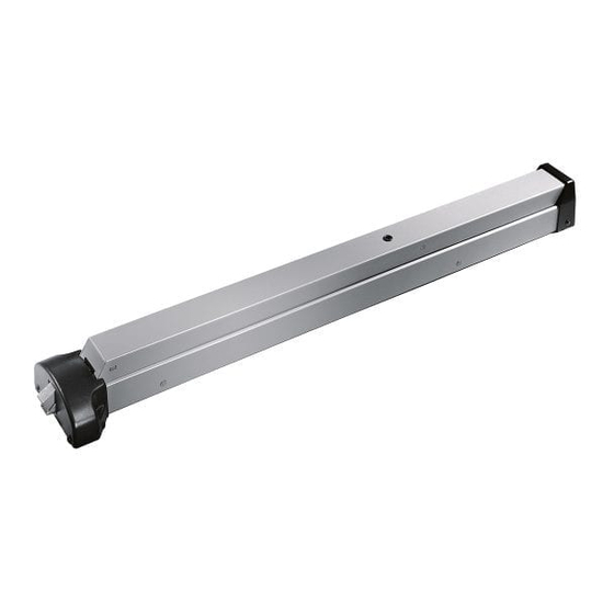
- Page 1 8300/F8300 Series Rim Exit Device Installation instructions 95011759 (1135-30) I8300-15 - 06-2020 | EN |...
- Page 2 8300/F8300 Exit Device Installation Instructions Table of Contents Table of Contents Overall Door preparation Prepare strike Drill door for exit device Verify door width Install strike and chassis (fire door) Install chassis, exit device and trim Install covers, end cap, end cover Install strike 1.10...
- Page 3 8300/F8300 Exit Device Installation Instructions Overall Overall End cap (2) #8 x 1” PHTS End cover Mounting plate 12-24 R.H.P.M.S (2) 8-32 x 1/4” PHTHMS Touch bar and rail assembly 8300 Series rim chassis assembly Dogging (omitted on F8300) 12-24 O.H.P.M.S.
- Page 4 8300/F8300 Exit Device Installation Instructions Door preparation Prepare strike Door preparation NOTE: SURFACE OF DOOR WHERE EXIT DEVICE IS TO BE INSTALLED MUST BE FLAT. PROPER REINFORCEMENT OF DOOR IS ALSO REQUIRED. NOTE: BEFORE STARTING INSTALLATION: 1. DOOR SHOULD BE FITTED AND HUNG.
- Page 5 8300/F8300 Exit Device Installation Instructions Drill door Verify door width Drill door for exit device NOTE: Vertical reference line is not centerline of cylinder Horizontal reference line Door Center line of chassis (Vertical reference units) 1.4.1 Refer to carton label for model and trim 1.4.3 Horizontal center line and center line of...
- Page 6 8300/F8300 Exit Device Installation Instructions Install strike and chassis (fire door) Install chassis, exit device, and trim Install covers, end caps, end covers Install strike and chassis (fire door) 1.6.2 Install strike angle using (2) 12-24 F.H.P.M.S. 1.6.1 When installing F8300 series device on fire and (2) 12-24 R.H.P.M.S.
- Page 7 8300/F8300 Exit Device Installation Instructions Install strike Options: cylinder dogging Install strike NOTE: BACKSET OF DEVICE SHOWN FOR 5/8” [16] HEIGHT STOP. 2-1/16” [53] 1.9.1 Install strike and adjust if necessary. Center line of strike No. 463 must line up with horizontal reference line on door.
- Page 8 DORMA USA, Inc. T: 800-523-8483 www.dormakaba.us...
Need help?
Do you have a question about the 8300 Series and is the answer not in the manual?
Questions and answers