Table of Contents
Advertisement
Quick Links
Saffire LX-D Installation Guide for door thickness
1 3/8" to 2 1/8"
For thicker door, please see order guide.
1.
Please read and follow all directions carefully.
2.
This lock is not designed to be used on emergency exit doors.
3.
Carefully inspect glass, door frame, door, etc. to ensure the recommended procedure will not cause damage.
dormakaba standard warranty does not cover damages caused by installation.
4.
Wear safety glasses when making the holes.
5.
All the following operations and testing of the lock are to be done with door open.
1A - INSTALL STRIKE ON WOOD FRAME
TOOLS REQUIRED
•
Safety glasses
For maximum
•
1/2" (13mm) Chisel
security, install
•
1/8" (3mm) Drill Bit
reinforcing
•
5/32" (4mm) Drill Bit
plate.
•
1" (25mm) Drill Bit or Hole Saw
•
2 1/8" (54mm) Drill Bit or Hole
Saw
•
Drill
•
Awl or Center Punch
•
Screwdriver, 1/8" Slotted
•
Philips Screwdriver #2
•
Adjustable Square
•
Tape Measure
1C - DOOR PREPARATION
A
1" (25mm)
2 1/8" (54mm) Hole saw
2.
ADJUST BACKSET OF DEADBOLT
2
1
3
DO NOT REMOVE TAPE
DEADBOLT IS PRE-SET AT 2 ¾" (70mm) BACKSET. PROCEED
AS SHOWN TO CHANGE TO 2 ⅜" (60mm) BACKSET, IF
REQUIRED.
WARNING
1B - INSTALL STRIKE ON STEEL FRAME
Install long screws
in door stop side
A = Backset = 2.3/4"(70mm) or 2 3/8" (60mm)
1.
Determine which template fits your Saffire LX-D lock installation, either
2 3/8" (60mm) or 2 3/4" (70mm) backset.
2.
Place appropriate template onto door and mark holes.
3.
Drill holes as per dimensions on the template. The 1" (25 mm) hole to
be on the center line of door thickness.
4.
Mortise door edge for dead bolt face plate.
5.
Drill 2 1/8" from both sides of the door to prevent unsightly damage.
3.
INSTALL DEADBOLT IN DOOR
DO NOT REMOVE TAPE
2X
SLOT AT THE BOTTOM
OR 2X
ITEM
QTY. DESCRIPTION
NO.
1
1
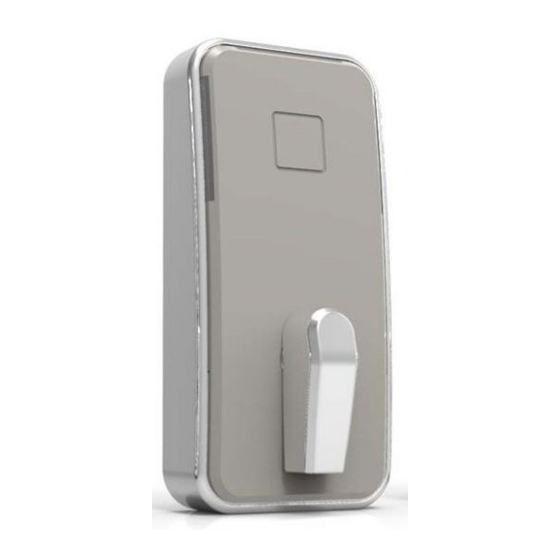
FRONT LOCK HOUSING ASSEMBLY
2
1
GASKET FRONT LOCK HOUSING
3
1
TAIL PIECE
4
1
INSIDE TRIM ASSEMBLY
5
1
INSIDE TRIM COVER ASSEMBLY
6
1
DEADBOLT
7
1
STRIKER PLATE
8
1
DUST BOX
9
1
REINFORCING PLATE
10
2
PHILLIPS, 8 X 1" WOOD SCREW
11
2
PHILLIPS, 8 X 3" WOOD SCREW
12
2
PHILLIPS, 8-32 X 7/32" FLAT HEAD SCREW
13
4
PHILLIPS, 8-32 X 1/2" FLAT HEAD SCREW
14
2
PHILLIPS, 8 X 1" WOOD SCREW
15
1
6-32 X 3/16" PAN DEAD SCREW
Door stop
16
3
PHILLIPS, 10-24 X 1-1/4" PAN HEAD SCREW
17
1
MESSENGER CABLE (OPTIONAL)
18
1
POWER CABLE
19
3
AA BATTERY
FOR DOOR THICKNESS BETWEEN 2-1/4" AND 2-1/2" PLEASE ORDER
HARDWARE KIT 062-515846.
12
10
9
8
7
11
dormakaba Canada inc.
7301 Boul Décarie
14
Montréal QC H4P 2G7
Canada
13
FOR STEEL DOOR
ITEM
QTY. DESCRIPTION
NO.
20
1
21
1
22
1
23
1
24
3
25
3
19
4
20
3
2
1
14
15
13
16
5
6
1-877-468-3555
www.dormakaba.us
FIRE PLATE
BASE PLATE
COVER PLATE
LOCATING POST
FLAT HEAD SCREW
BUTTON HEAD SCREW
PART LIST & LOCK DIAGRAM
HORIZONTAL MOUNTING
OPTION
INSIDE TRIM
22
23
24
21
25
Please continue on next page.
Advertisement
Table of Contents

Subscribe to Our Youtube Channel
Related Manuals for Dormakaba Saffire LX-D


Summary of Contents for Dormakaba Saffire LX-D
- Page 1 1C - DOOR PREPARATION A = Backset = 2.3/4"(70mm) or 2 3/8" (60mm) Determine which template fits your Saffire LX-D lock installation, either 2 3/8" (60mm) or 2 3/4" (70mm) backset. Place appropriate template onto door and mark holes.
- Page 2 4. ADJUST LOCK HANDING ON OUTSIDE HOUSING ASSEMBLY 8A - INSTALL INSIDE TRIM ASSEMBLY (VERTICAL MOUNTING ONLY) - FOR HORIZONTAL MOUNTING SEE 8B - SHEET 3 THEN PROCEED WITH SECTION 9. HOLD INNER CAM IN PLACE, INNER CAM GROOVE ORIENTED AT 12 O'CLOCK. INSTALL INSIDE TRIM ON DOOR AS SHOWN BELOW, RUNNING CABLES THROUGH INSIDE TRIM BACKPLATE LOWER SLOT.
- Page 3 8B - INSTALL INSIDE TRIM ASSEMBLY HORIZONTAL MOUNTING OPTION (IF APPLICABLE) COVER PLATE AND INSIDE TRIM ASSEMBLY SHALL BE INSTALLED AS SHOWN WITH 3X SCREWS, ITEM 25. BEFORE TIGHTENING THE SCREWS VERIFY FUNCTIONALITY BY EXTRACTING AND RETRACTING THE DEADBOLT. DEADBOLT SHALL MOVE SMOOTHLY.
- Page 4 INSIDE TRIM COVER INSTALLATION, FOR MORE DETAIL PLEASE SEE SAFFIRE LX-D INSTALLATION GUIDE DETAIL B STEP 1 STEP 1 TAIL PIECE SHALL BE IN VERTICAL POSITION & KNOB IN HORIZONTAL POSITION. KNOB RH INSTALLATION LH INSTALLATION DETAIL A STEP 1: ENGAGE TAIL PIECE STEP 4: CLOSE COVER'S BOTTOM.
Need help?
Do you have a question about the Saffire LX-D and is the answer not in the manual?
Questions and answers