
Related Manuals for Eaton Crouse-Hinds 9373-FB3 Series


Summary of Contents for Eaton Crouse-Hinds 9373-FB3 Series
- Page 1 Instruction manual June 2020 MTL fieldbus networks INM MTL9373-FB3 Rev 1 9373-FB3 MTL Compact Fieldbus Barrier System...
-
Page 2: Table Of Contents
CONTENTS DECLARATION OF CONFORMITY A printed version of the Declaration of Conformity has been provided separately within the original shipment of DECLARATION OF CONFORMITY........ii goods. -
Page 3: General Safety Information
• No changes to any of the components that might impair their explosion protection are permitted. If any information provided here is not clear: Contact Eaton’s MTL product line or one of its representatives. NOTE Improper installation and operation of the module can result in the invalidation of the guarantee. -
Page 4: Overview
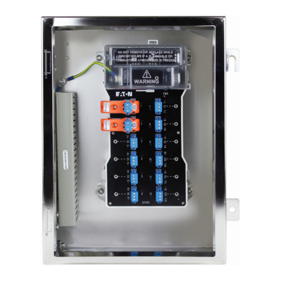
MTL9373-FB3-Px-SS-12 spur DESCRIPTION Compact Fieldbus Barrier System The 9373-FB3-Px-SS is a third-generation product, in a successful range of Eaton - MTL Fieldbus Barrier Systems. The field-mounted enclosure contains a barrier that receives power and FOUNDATION Fieldbus H1 communications via a non-intrinsically safe trunk and converts this to a number of galvanically isolated, intrinsically safe, spur connections. -
Page 5: Permitted Configurations
PERMITTED CONFIGURATIONS MECHANICAL INSTALLATION See Figure 4.1 and 4.2 below for the dimensions, fixing locations and cable A maximum of two 12-spur, Fieldbus Barrier modules is permitted per Fieldbus trunk. gland positions of the two main enclosure options. The permitted options are illustrated in Figure 3.1 - (a), (b) and (c). a) A single barrier module in a field enclosure - with termination (362 - Wall xing centres) ( 152 ) -
Page 6: Mounting Overview
Mounting overview Before mounting an enclosure, be aware of and check the following points. a) The enclosure is designed for mounting on a vertical surface, with the cable entry at the lowest point, as shown in the upper part of Figures 4.1. and 4.2. The permitted ambient temperature range in this orientation (–20°C to +60°C), external to the enclosure, must not be exceeded. -
Page 7: Mounting
Mounting ELECTRICAL INSTALLATION WARNING! WARNING! Before starting any electrical installation work, ensure that the To minimise the risk of ignition by electrical apparatus incoming trunk connection is isolated from any source of power. in hazardous areas, efficient installation, inspection and maintenance of apparatus and systems is essential, and the CAUTION! work should be carried out by suitably trained personnel in... -
Page 8: Cable Shield Grounding
5.2.2 Cable shield grounding Trunk cable wiring The cable shield is normally electrically isolated from the protective earth ground, although the two may be deliberately interconnected in some The 9373-FB3-PX-SS product has a range of user options for trunk wiring. These grounding arrangements, as described below. -
Page 9: Standard Large Enclosure - Trunk Wiring Details
In each case the active trunk cable is wired directly to the ‘TRUNK IN’ Fieldbus Connect the prepared ends of the incoming fieldbus trunk cable into the + Barrier terminals. , – and ‘S’ terminals of the ‘TRUNK IN’ connector – see Figure 5.6 - observing colour coding in accordance with site wiring regulation. -
Page 10: Active Trunk Cable Wiring
5.5.1 Active trunk cable wiring 5.5.2 Spare trunk cable management As stated above, the Standard Large enclosure has provision for additional NOTE terminals to manage both trunk surge suppression wiring and additional (spare) trunk cabling – see Section 5.5.2 for details of the spare cable management. If the trunk cable entering the enclosure has no spare wires requiring On this enclosure, the surge suppressor is wired into the extra DIN-rail management, ignore this section and move on to Section 5.5.3... -
Page 11: Trunk Termination
5.5.3 Trunk Termination Spur wiring connections Refer to Figures 5.11 for additional details. The Fieldbus Barrier has a built-in terminator facility that is used when the module is the last, or only, barrier on the trunk. The terminator is ‘activated’ by positioning the link on the right, as shown in Figure 5.10 below. -
Page 12: Final Checks
MAINTENANCE Final checks Before fitting/closing the lid on the barrier enclosure, check that: When an enclosure containing a Fieldbus Barrier module is installed in a hazardous • all wire terminal connection screws are sufficiently tightened. area it is important for personnel to understand what activities are permissible when fieldbus power is present and what are not. -
Page 13: Trunk Connections
Trunk connections Use the following procedure and reference to Section 5.3.1 may help. a) Unclip and remove the Trunk Terminal cover Note the warning given on the covers protecting all of the trunk wiring areas. b) Loosen the two screws securing the pluggable, TRUNK-IN wiring connector and unplug it. -
Page 14: Regular Maintenance Checks
Regular Maintenance checks 1) Disconnect the red (+), black (–) and yellow/green wires of the TP-32 module. The + and – will either be on the Fieldbus Barrier or on the DIN rail terminals, Check the general condition of the installation occasionally to ensure that no depending upon the enclosure type. -
Page 15: Atex Information
ATEX INFORMATION NOTE The Essential Health and Safety Requirements (Annex II) of the EU Directive The Power LED will not light until the voltage at the barrier has risen to a value of 2014/34/EU [the ATEX Directive - safety of apparatus] requires that the installation at least 15.7V, but could remain lit even after the voltage has dropped to around manual of all equipment used in hazardous areas shall contain certain information. -
Page 16: Inspection And Maintenance
Notified Body Identification Number. This information applies to products manufactured during or after the year 2019. For full certification information visit Eaton’s MTL products website at : www.mtl-inst.com/resources/datasheets Search on the product family name and type number to view datasheets and certificates. - Page 17 MTL Instruments GmbH, Heinrich-Hertz-Str. 12, 50170 Kerpen, Germany UNITED ARAB EMIRATES Cooper Industries/Eaton Corporation Tel: +49 (0)22 73 98 12 - 0 Fax: +49 (0)22 73 98 12 - 2 00 Office 205/206, 2nd Floor SJ Towers, off. Old Airport Road, E-mail: csckerpen@eaton.com...
Need help?
Do you have a question about the Crouse-Hinds 9373-FB3 Series and is the answer not in the manual?
Questions and answers