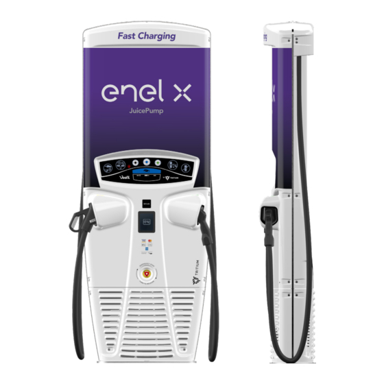
Enel X JuicePump Installation Manual
50kw dc
Hide thumbs
Also See for JuicePump:
- Installation manual (35 pages) ,
- User & installation manual (20 pages) ,
- Manual (16 pages)

Related Manuals for Enel X JuicePump


Summary of Contents for Enel X JuicePump
- Page 1 Installation Manual TRI93-50-01-UL 50kW DC www.enelx.com Phone: +1-844-584-2329...
-
Page 3: Table Of Contents
Contents Important safety instructions and specifications. Save these instructions......1 FCC Notice..........................3 Packaging, handling & receipt....................4 Site configuration........................5 Underground power preparation...................9 Above ground power preparation..................10 Installation requirements & equipment................11 Unpacking & installation preparation...................13 Installation..........................16 Underground conduit and wiring..................18 Above ground conduit and wiring..................20 Wire &... -
Page 4: Important Safety Instructions And Specifications. Save These Instructions
18 AWG Use 90°C Copper Wire CAUTION An insulated grounding conductor that is The JuicePump fast charger must be identical in size, insulation material and installed and serviced only by qualified thickness to the grounded and electrical personnel. To achieve EMC... - Page 5 3ø WYE CONNECTED 277/480V ±10% 60Hz 55kW 1ø, 120V 60Hz 250W The JuicePump must be connected to a circuit provided with appropriate branch circuit over-current protection in accordance with the National Electrical Code, ANSI/NFPA 70. Tightening torque: Wiring terminals: Breaker 4.0 Nm/35 lb-in...
-
Page 6: Fcc Notice
Warning: Any changes or harmful interference when the equipment modifications not expressively is operated in a commercial environment. approved by (Enel X) could void This equipment generates, uses and the user’s authority to operate this can radiate radio frequency energy and,... -
Page 7: Packaging, Handling & Receipt
Packed crate weight: In all cases, the JuicePump is to be transported to the installation site in its 200kg/440lb original packaging and only unpacked at the installation site. -
Page 8: Site Configuration
6 meters/20ft of an outdoor Ground fixing: motor fuel dispensing device. The JuicePump is to be fixed to the ground through the baseplate fixing holes with 4 x M16 or 5/8-11 inch fasteners (not supplied). The fasteners should... - Page 9 Site configuration Minimum measurement requirements: Contact your Enel X representative for installation advice if your mimimum measurements are smaller than shown in Figure 1. 9.8” (250) 6.3” Wall Wall 28.5” (725) 11.8” 28.5” (725) minimum (300) minimum Figure 1. Dimensions walls or obstacles Do not scale www.enelx.com...
- Page 10 If longer length cables are used please If the JuicePump is to be installed with it’s ensure the cable is kept tidy and close back or sides against or near a wall or to the JuicePump sides at all times.
- Page 11 When being installed back to back, a A additional space of 700mm/27.5 inches minimum distance of 300mm/12 inches from the center front of the baseplate is between the JuicePump chargers is required to open the front panel for recommended. servicing, as shown in Figure 4.
-
Page 12: Underground Power Preparation
Underground power preparation If a concrete foundation is being pre- precisely located in the 50mm power hole pared to bring power into the JuicePump location in relation to the mounting studs. through the baseplate, use the following This ensures the sealing of the supplied as a guide for preparation. -
Page 13: Above Ground Power Preparation
Figure 7. Top view the JuicePump above ground, the conduit 1 metre/3 feet will enter the JuicePump via the back radiator panel on the left hand side as shown in Figure 6. Use the JuicePump template (supplied in the crate kit) or or measure as per Figure Back 5, to ensure the fixing points are correct. -
Page 14: Installation Requirements & Equipment
JuicePump. Baseplate template The JuicePump must be installed and The JuicePump is shipped with a tem- serviced by qualified electrical personnel. porary single phase power cable which allows the unit to be powered prior to Observe all pertinent national, regional, installation. - Page 15 Installation requirements & equipment Required equipment: Lifting apparatus. See pg 4 for weights. Ensure lifting apparatus is sufficiently rated. For height restricted areas alternative lifting methods are available. Contact your supplier for more information. 4x M16 or 5/8 glavanised or SS washers 4x M16 or 5/8-11 galvanised nuts to match fasteners.
-
Page 16: Unpacking & Installation Preparation
2. Lift Veefil-RT to vertical Securely attach the lifting straps at the Move the crate as close to the top of the JuicePump to the lifting appa- prepared installation site as possible. ratus and gently raise to a standing posi- Ensure there is enough room to tion on the shipping baseplate. - Page 17 3. Remove front and rear radiator Removing the radiator from the base of panels the JuicePump gives more space for bringing power into the unit, however, removing the radiator is not always If access to the rear radiator panel is required.
- Page 18 Unpacking & installation preparation The radiator cooling system must be disengaged from the unit. Unclip the two quick release parts. One is on the base behind the radiator, the other is on the left side with the expansion bag. NOTE: Do not twist or pull on the tubing engaged with the metal quick release parts.
-
Page 19: Installation
Installation 1. Secure to foundation 3. Place front panel on ground Lift the JuicePump by the supplied lifting The front panel is attached to the straps, place onto the prepared enclosure with wiring and an earthing foundation and secure with the specified strap on the front left hand side. - Page 20 Ensure this is carefully stored to avoid damage or accumulation of debris. 6. Pre-installation power up The JuicePump is shipped with a tem- porary single phase power cable which allows the unit to be powered prior to installation. This is attached to the M40 blanking plug.
-
Page 21: Underground Conduit And Wiring
Underground conduit and wiring The JuicePump is supplied with a Flexa conduit system in the crate kit, with all parts attached. conduit coupling washer 6” conduit flex flexa flex locking nipple adapter conduit adapter ring 1. Disassemble the Flexa system 2. - Page 22 Underground conduit and wiring 3. Prepare remaining Flexa system Remove the locking ring from the remaining section of the Flexa system. Push the flexa conduit into the installed flex adapter to attach. Attach the top flex adaptor into the hole inside the service hatch with the washer on the outside of the box, and secure inside with the locking ring.
-
Page 23: Above Ground Conduit And Wiring
Above ground conduit and wiring 1. Disassemble the Flexa system 3. Attach Flexa conduit Remove the end flex adapter by pushing Feed the Flexa conduit (not supplied) in the ring of the conduit fitting, and from the rear left of the unit and press fit pulling out the conduit. -
Page 24: Wire & Commission
Wire & commission CAUTION CAUTION Wiring and commissioning the charger is When the wiring and cabling is connect- to be done by qualified electrical ed, refit the service cover BEFORE you personnel only. turn on power supply to the charger. The wiring diagram is also available on The power supply to the charger should the inside of the Service Hatch. - Page 25 Wire & commission Bend the wires to the side of the ferrite Trim the wires leaving a minimum of rings and up into the connection points. 300mm/12 inches exposed. Check that the wiring is sitting behind the lower face of the switch gear so they will Single phase wires thread through the not interfere with the service cover.
-
Page 26: Ethernet Port Access
Ethernet port access The Ethernet port is situated under the enclosure box on the back left. The rear radiator panel must be removed to access this location. Twist to disengage the cap and plug in the ethernet cable. If hardwiring in the ethernet cable, please see page 5 for connector details. -
Page 27: Closing Checklist
Closing checklist Once the charger has been commissioned Check the gasket has not been damaged the unit requires re-assembly and closing or soiled. If using a power drill to fasten prior to operation. the nuts ensure the correct torque setting Follow these steps in order to ready of no greater than 2.0 Nm/17.70 lb-in. - Page 28 Do not over tighten. If the power is above ground, the rear radiator panel provides the exit point for the conduit from the JuicePump. Cut the four tabs on the lower right hand of the radiator panel to remove the material to open the conduit exit point.
-
Page 29: Installation Checklist
5mm Pin Hex tool ensuring the plastic holes line up with the bracket nutserts. Do not over tighten. 9. Complete installation checklist Complete the JuicePump Site Installation Checklist, and return to Enel X. This must be returned for warranty vali- dation.
Need help?
Do you have a question about the JuicePump and is the answer not in the manual?
Questions and answers