Table of Contents
Advertisement
Quick Links
Advertisement
Table of Contents

Related Manuals for Enel X Waypole


Summary of Contents for Enel X Waypole
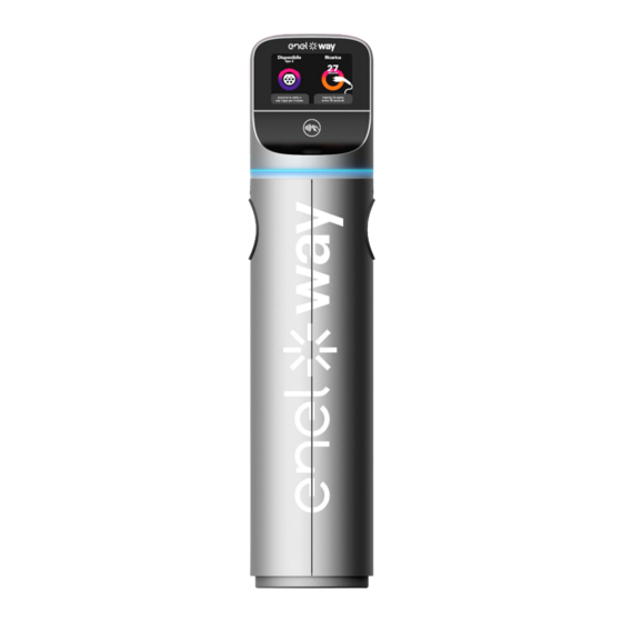
- Page 1 Waypole User Manual ENGLISH...
-
Page 2: Table Of Contents
Contents 1. Purpose 2. Field of application 3. Definitions/Abbreviations 4. Waypole 4.1 Dimensions 4.2 Specifications 4.3 Functionality 4.4 The user interface 4.5 Operation 4.5.1 Introduction 4.5.2 Charging 4.5.3 Exceptions Appendix A... -
Page 3: Purpose
1. Purpose The purpose of this document is to describe how to use the equipment named Enel X Way Waypole™. 2. Field of application It is used to document how to use such equipment as part of an Electric Vehicle Charging System. -
Page 4: Waypole
4. Waypole 4.1 Dimensions There are several versions of the Enel X Way Waypole™: 1. Three-phase/Three-phase with 2 T2 sockets; 2. Single-phase/Three-phase with 1 T3a socket and 1 T2 socket; 3. Single-phase/Single-phase with 2 T3a sockets. These variants affect the user, especially regarding the type of power supply cable provided with the Electric Vehicle. -
Page 5: Specifications
4.2 Specifications POWER SUPPLY VOLTAGE 400 Vac Three-phase FREQUENCY 50 Hz CHARGING DATA Type 3A socket with 4 contacts L, N, EARTH + Pilot Maximum power 3,7 kW Maximum current 16 A SINGLE- = 16 A PHASE CHARGING Thermal-magnetic protection = 10kA Type “D”... -
Page 6: Functionality
> EN62196-1 4.3 Functionality The Waypole was designed for charging “Class I” Electric Vehicles. It supplies 230 Vac single-phase with a maximum power of 3.7 kW and/or 400 Vac three- phase with a maximum power of 22 kW. It works in “Mode 3” and is connected to the vehicle as described in the EN61851-1 standard (Ed. -
Page 7: The User Interface
NOTE: The user should note that the ”pilot control wire” in the power supply circuit prevents the Waypole from supplying power until the plug is fully inserted into the socket. - Page 8 RH indicator LH indicator RH socket LH socket Card Reader...
-
Page 9: Operation
4.5 Operation 4.5.1 INTRODUCTION The Waypole control system manages both the RH and LH sockets in parallel, making it possible to charge two EVs simultaneously. 4.5.2 CHARGING The display initially looks like this (assuming that there is no charging in progress): First, users must identify themselves with the RFID card or appropriate APP. - Page 10 If the system accepts the RFID card, this appears: It is then necessary to insert the plug on the charging cable into the chosen socket within 90 seconds (timeout). The following screens will “alternate” cyclically. When only 30 seconds remain, the screen will show a numerical countdown (see the red arrow).
- Page 11 Suppose we insert the plug into the RH side; the display will show: As soon as charging starts, the screen will show the kWh supplied on the side in which the plug is inserted, e.g. RH. If a second valid RFID card is brought up to the reader (or using an appropriate APP) while the charging just started is in progress, the following appears in sequence: It is now necessary to insert the plug on the charging cable into the LH socket (last available) within 90 seconds (timeout).
- Page 12 Suppose that the charging on the RH side is stopped by bringing the card up to the RFID reader (or using the appropriate APP); the following will appear in sequence: The system will stop supplying power from the side corresponding to the RFID card used, and gives a summary of the Wh supplied during charging.
-
Page 13: Exceptions
Lastly, suppose that the charging on the RH side is also terminated by bringing the card up to the RFID reader; the following will appear in sequence: The system will stop supplying power from the side corresponding to the card used, and gives a summary of the Wh supplied during charging. - Page 14 > Charging interrupted -> Remove the plug to finish. > Charging interrupted -> Bring the card close or use the App to end. > Standby: charging suspended by the centre -> Wait for charging to continue. > Standby: charging suspended by the EV (batteries overheated) -> Wait for charging to continue.
- Page 15 > Plug inserted without card validation -> Remove the plug > Communication problems with the centre -> Charging will end when the indicated time expires if the communication problems are permanent (e.g. 15 minutes). > (105:) Problems with the centre -> Not possible to continue.
- Page 16 THE MESSAGES ARE CODED AS FOLLOWS CODE MESSAGE SIGNIFICANCE Invalid card Not possible to continue. Validation not successful Not possible to continue. Problems with the centre - > Not Validation failed possible to continue. Communication problems with the Centre disconnected centre ->...
- Page 17 Invalid card -> Not possible to No associated stakeholder continue. Invalid card -> Not possible to Incorrect CU type continue. Invalid card -> Not possible to Incorrect POD continue. Invalid card -> Not possible to Out of province continue. Socket booked Not possible to continue.
- Page 18 Appendix A Error codes Messages appear on the display together with an “Error Code” (see the blue arrow) if errors occur during normal Waypole operation. The table below lists all the possible error codes with their meanings and possible solutions. EVENT...
- Page 19 CM is not operational + Switch the PS off and on No mains power again CM is not operational + Switch the PS off and on Internal flash memory full again + Ask + No mains power the centre to erase Communication problem Switch the PS off and on with the card...
Need help?
Do you have a question about the Waypole and is the answer not in the manual?
Questions and answers