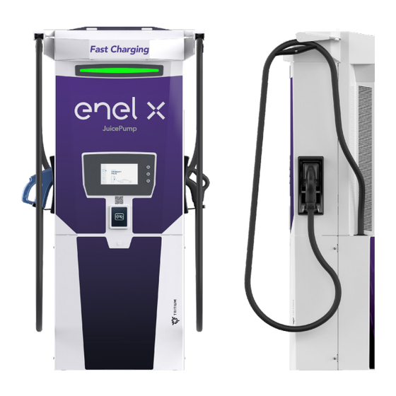
Enel X JuicePump User & Installation Manual
Hide thumbs
Also See for JuicePump:
- Installation manual (35 pages) ,
- Manual (16 pages) ,
- Operating manual (12 pages)
Subscribe to Our Youtube Channel
Summary of Contents for Enel X JuicePump
- Page 1 User Unit Installation Manual TRI125-175-S (USA) 175 kW DC www.enelx.com Phone: +1-844-584-2329...
-
Page 3: Table Of Contents
Contents Important safety instructions....................1 Packaging, handling, & receipt....................4 Site configuration........................5 Site survey.......................5 Ground fixing....................5 Conduit requirement..................5 Foundation requirements.................5 Communications....................5 Servicing distance....................6 Cable range......................6 Baseplate dimensions......................7 Installation requirements & equipment.................8 Unpacking..........................9 Installation..........................10 Wiring and commissioning....................12 Ethernet port access......................14 Fiber optic access.........................15 Closing checklist........................16 www.enelx.com Phone: +1-844-584-2329... -
Page 4: Important Safety Instructions
Symbol To achieve EMC compliance, the chassis Wiring of the JuicePump user unit must be bonded to Earth locally at the charger. Power and Protective Earth (PE) Conduc- tor ratings: DC Copper 95 mm2 (cross section), V90 class, rated to operate at Grounding instructions 90°C. - Page 5 Important safety instructions SAVE THESE INSTRUCTIONS Usage limitations Warning Cord extension sets or second Installation shall not be made in a cable assemblies shall not be used commercial garage (repair facility) or in addition to the cable assembly for closer than 6,096 mm / 20 feet of an the connection of the vehicle to the outdoor motor fuel dispensing device.
- Page 6 Important safety instructions SAVE THESE INSTRUCTIONS FCC Notice Information to the User (FCC Part 15.105) Class A product: NOTE: This equipment has been tested and found to comply with the limits for a Class A digital device, pursuant to part 15 of the FCC rules.
-
Page 7: Packaging, Handling, & Receipt
Installation, commissioning, and servicing Packed crate weight of the JuicePump user unit should only be carried out by qualified personnel. 300 kg / 660 lbs (approx) Materials Crate size... -
Page 8: Site Configuration
A site can utilize Ethernet or optical fiber between the IPU and UU. If the UU and The JuicePump user unit is to be fixed to IPU are configured for use of optical fiber, the ground through the baseplate fixing then use optical fiber. -
Page 9: Servicing Distance
Servicing distance An additional space of 700 mm / 27.559 inches from the front and rear of the JuicePump user unit is required to open the front panel for servicing, as shown in the image below. 700 mm / 27.559 inches 700 mm / 27.559 inches... -
Page 10: Baseplate Dimensions
Baseplate dimensions 300 / 11.811 36 / 1.417 165 / 6.496 236 / 9.291 Note: Do not scale. All dimensions shown in millimeters (mm)/inches (in). A mounting stencil may be supplied by the manufacturer at customer re- quest. www.enelx.com Phone: +1-844-584-2329 TRI125.INS.036.3... -
Page 11: Installation Requirements & Equipment
• Socket set & ratchet • Torque wrench with 30 Nm setting The JuicePump user unit has an IP65 • Torque wrench with 2 Nm setting electronics enclosure rating, however, as • 1 x M8 lug for ground wire... -
Page 12: Unpacking
Do not work under suspended loads. Securely attach the lifting straps at the top of JuicePump to the lifting apparatus Two people may be required as the unit and gently raise to a standing position on may swing. -
Page 13: Installation
2. Remove rear lower panel 4. Secure to foundation Follow this step to increase visibility and Lift the JuicePump user unit and place access to the mounting holes. If visibility over the prepared foundation. Feed the and access is sufficient, go to step 3. - Page 14 Each installation busbar is fitted with M10 screws with the 4 mm allen key to pre- fasteners. Remove the fasteners ready for pare the JuicePump for wiring installation. wiring in. The enclosure access cover has an attached gasket. Ensure this is carefully...
-
Page 15: Wiring And Commissioning
Note: Refer to the TRI125.INS.018 CRITICAL JuicePump RT 175-S Site Installation Manual for a table of all torques used during installation. Clean the surface areas of the mating surfaces with an abrasive pad and... - Page 16 Wiring & commissioning Note: For all field wiring terminal connections, refer to the wiring diagram CRITICAL sticker on the inside of the Service Hatch. 2. Single phase power If the single-phase wiring is run in a three-core cable (2C+E), do not The single-phase power field wiring terminate the third core (earth) to the terminals are located on the underside of...
-
Page 17: Ethernet Port Access
Ethernet port access The Ethernet port is situated on the front of the enclosure box. Twist to disengage the base cap and wire in the Category 6a STP Ethernet cable. Ensure the base cap is securely fitted back into the holder for IP65 protection. CAUTION To ensure the stability of communication to the user unit, it is important that when... -
Page 18: Fiber Optic Access
Ethernet port of the user unit. Ensure that the coupling ring is tight, so that when the fiber optic cable is connected, the connection is tight. For detailed wiring instructions, see TRI125.INS.016 JuicePump RT 175-S Pip- ing and Cabling . www.enelx.com Phone: +1-844-584-2329 TRI125.INS.036.3... -
Page 19: Closing Checklist
Closing checklist 3. Attach the rear lower panel Follow these steps in order to ready the unit for commissioning: Lift the panel and slide it over the 1. Remove lifting straps fixing points and rubber cable flanges on both sides until it is secure under the top Carefully remove the lifting straps from panel and flush against the enclosure. - Page 20 Closing checklist 4. Plug in the parking sensor 5. Attach the front lower panel The JuicePump user unit has a parking Raise and slide the front lower panel into sensor available for use on the front lower the fixing points located under the front panel.


Need help?
Do you have a question about the JuicePump and is the answer not in the manual?
Questions and answers