
Related Manuals for Enel X JuicePump 150


Summary of Contents for Enel X JuicePump 150
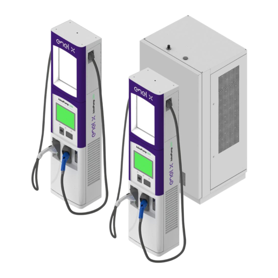
- Page 1 JuicePump 150 INSTALLATION AND USER’S MANUAL WWW.ENELX.COM PHONE NUMBER:+1-844-584-2329...
- Page 2 150 INSTALLATION AND USER’S MANUAL PLEASE NOTE This document contains useful general information about the product and its installation. Enel X. reserves the right to make changes to this product without further notice. No part of this document may be reproduced in any form or by any means, electronic or mechanical, including photocopying, without written permission of Enel X.
-
Page 3: Table Of Contents
Page 3 of 68 JuicePump TABLE OF CONTENTS 150 INSTALLATION AND USER’S MANUAL Table of Contents Safety Guidelines ........................5 1.1. Important Safety Instructions ....................5 1.2. Symbols and Definitions ......................6 System Overview ........................7 Equipment Description ......................8 System Specification ...................... - Page 4 Page 4 of 68 JuicePump TABLE OF CONTENTS 150 INSTALLATION AND USER’S MANUAL Table of Contents (Continuation) 9.2.2. CCS1 Connector (500 A) ..................... 41 9.2.3. CCS1 Connector (200 A) ..................... 41 9.3. Operating Instruction ......................42 9.4. Troubleshooting ........................46 Maintenance ........................
-
Page 5: Safety Guidelines
In situations where it is not possible to perform an installation following the procedures stated in this document, contact Enel X. Enel X will not be responsible for any damages that may occur resulting from custom installations that are not stated in this document. -
Page 6: Symbols And Definitions
Page 6 of 68 JuicePump 150 SAFETY GUIDELINES INSTALLATION AND USER’S MANUAL 1.2. Symbols and Definitions Please take special attention to all information marked with the following symbols. These symbols may be found throughout the manual and on labels affixed to the equipment unit. -
Page 7: System Overview
INSTALLATION AND USER’S MANUAL System Overview The JuicePump 150 converts a 480VAC 3-phase voltage into DC voltage to directly charge an electric vehicle’s lithium-ion battery. It is capable to charge all electric vehicles compliant with CHAdeMO charging system and Combined Charging System (CCS) standards. -
Page 8: Equipment Description
Page 8 of 68 JuicePump 150 EQUIPMENT DESCRIPTION INSTALLATION AND USER’S MANUAL Equipment Description 150 kW HIGH POWER UNIT / TOWER COMPONENT DESCRIPTION 1. 50KW #3 Power Module Master Controller 2. 50KW #2 Power Module Safety Relays 3. 50KW #1 Power Module 10. - Page 9 Page 9 of 68 JuicePump 150 EQUIPMENT DESCRIPTION INSTALLATION AND USER’S MANUAL 350A / 200A CHARGE DISPENSER COMPONENT DESCRIPTION 15-inch Outdoor-Rated Display and Customer Advertising Panel Touch Screen Start Button / Function Key 1 Magnetic stripe Credit Card Reader Stop Button / Function Key 2 RFID Card Reader 10.
- Page 10 Page 10 of 68 JuicePump 150 EQUIPMENT DESCRIPTION INSTALLATION AND USER’S MANUAL SYSTEM COMPONENTS Power Unit / Tower ITEM DESCRIPTION MODEL NUMBER DCFC Power Unit Dual Output, SCCR 65kA EVPC-150-2-480-3-65 HPCT-150-480-2 Dispenser ITEM DESCRIPTION MODEL NUMBER DCFC 350A Dispenser, CCS/CHAdeMO...
-
Page 11: System Specification
Page 11 of 68 JuicePump 150 SYSTEM SPECIFICATION INSTALLATION AND USER’S MANUAL System Specification 4.1. DCFC Power Unit AC to DC Power Converter Specification Model Number: EVPC-150-2-480-3-65 SKU: HPCT-150-480-2 PARAMETER 150kW POWER UNIT / TOWER AC Input Input Voltage Range... -
Page 12: Dcfc Dispenser
Page 12 of 68 JuicePump 150 SYSTEM SPECIFICATION INSTALLATION AND USER’S MANUAL 4.2. DCFC Dispenser High Power Dispenser Specification Model Numbers: EVDSP-350-5-120-0-2-C-4-0, EVDSP-350-4-120-0-2-C-4-0 EVDSP-200-5-120-0-2-C-4-0, EVDSP-200-4-120-0-2-C-4-0 SKUs: HPCD1-350-01-003, HPCD1-350-02-003, HPCD1-200-01-003, HPCD1-200-02-003 DISPENSER PARAMETER 350A Rated 200A Rated AC Input Auxiliary Input Voltage... -
Page 13: Pre-Installation
Conformance to all governing standards for location and placement of the charger • Communications Connectivity o Refer to Enel X guidelines in “Determining Suitability of Site for Cellular Connectivity” o Ensure that installation location meets the Cellular Signal Strength Criteria below Parameter... -
Page 14: Cable Reach
Page 14 of 68 JuicePump 150 PRE-INSTALLATION INSTALLATION AND USER’S MANUAL 5.2. Cable Reach The cables of the dispenser come in different lengths depending on the dispenser configuration and cable/connector type. The table below shows the connector type with its corresponding cable reach while the figure shows the radius in which the two (2) DC connectors can be used. -
Page 15: Ada Consideration
Page 15 of 68 JuicePump 150 PRE-INSTALLATION INSTALLATION AND USER’S MANUAL 5.3. ADA Consideration STANDARDS FOR ACCESSIBLE DESIGN for Americans with Disabilities is applicable when choosing the location and placement of all Electric Vehicle Supply Equipment. The following is a direct excerpt from the 2010 ADA Standards for Accessible Design: http://www.ada.gov/2010ADAstandards_index.htm... - Page 16 Page 16 of 68 JuicePump 150 PRE-INSTALLATION INSTALLATION AND USER’S MANUAL For information about the ADA, including the revised 2010 ADA regulations, please visit the Department’s website www.ADA.gov; or, for answers to specific questions, call the toll-free ADA Information Line at 800- 514-0301 (Voice) or 800-514-0383 (TTY).”...
-
Page 17: List Of Parts, Materials, And Tools Needed For Installation
Page 17 of 68 JuicePump 150 PRE-INSTALLATION INSTALLATION AND USER’S MANUAL 5.4. List of Parts, Materials, and Tools Needed for Installation Parts & Materials Needed to Purchase Item Part Description Quantity Remarks OM3, multimode, 50/125µm, 2 pairs per Recommended supplier:... -
Page 18: Transportation And Handling
Page 18 of 68 JuicePump 150 TRANSPORTATION AND HANDLING INSTALLATION AND USER’S MANUAL Transportation and Handling 6.1. Packaging The power unit/tower and dispenser are packaged, shipped, and delivered in wood crates. Below are the details of its packaging and dimensions for both tower and dispenser. -
Page 19: Receiving And Unpacking
Tip N Tell tilt indicator. Provide information of the damage as detailed as possible. • For any issues or questions regarding the shipment, please call Enel X Shipment In-charge at (714) 706 – 4970. Initial Release... -
Page 20: Installation
INSTALLATION INSTALLATION AND USER’S MANUAL Installation SAFETY INSTRUCTIONS The JuicePump 150 should be installed in accordance with local codes and all applicable ordinances. Read all installations instructions carefully prior to performing the installation. DANGER The equipment utilizes high voltages, only qualified electrical personnel familiar with the operation and construction should install, adjust, modify, and service this equipment. -
Page 21: Moving And Hoisting Instructions
Page 21 of 68 JuicePump 150 INSTALLATION INSTALLATION AND USER’S MANUAL 7.1. Moving and Hoisting Instructions CAUTION Improper handling may result to severe injury and/or damage to the unit due to dropping or falling. Make sure to follow specified procedures for hoisting operations. Take necessary measures to prevent falling when moving or hoisting the unit. - Page 22 INSTALLATION INSTALLATION AND USER’S MANUAL Enel X’s recommendation in reference to the M12 lifting eye bolt specification and the charger’s maximum weight, is to use all four (4) eye bolts and keep the vertical angle between 0° to 15° when lifting.
- Page 23 Page 23 of 68 JuicePump 150 INSTALLATION INSTALLATION AND USER’S MANUAL NOTE After the Power Unit / Tower is fixed on its location, the lifting eye bolts must be removed, and end sealing protections must be inserted into the holes.
-
Page 24: Mounting Procedures
Page 24 of 68 JuicePump 150 INSTALLATION INSTALLATION AND USER’S MANUAL 7.2. Mounting Procedures 7.2.1. Clearance Around the Unit Clearance surrounding the unit must be considered for proper ventilation and service accessibility. Refer to the installation drawings as illustrated below. -
Page 25: 7.2.2. Tower And Dispenser Mounting
Page 25 of 68 JuicePump 150 INSTALLATION INSTALLATION AND USER’S MANUAL Dispenser Installation Drawing 7.2.2. Tower and Dispenser Mounting Both the Tower and Dispenser must be fixed on a concrete pad using four (4) ½" x 4" (P/N RHPA- 3830) concrete expansion bolts or as determined appropriate by the structural engineer in- charge. - Page 26 Page 26 of 68 JuicePump 150 INSTALLATION INSTALLATION AND USER’S MANUAL Power Unit / Tower Footer Drawing The illustration below shows the drilling layout for the Power Unit / Tower. Only four (4) points are needed to fix the unit on the concrete pad. The conduit entry to the unit is also shown.
- Page 27 Page 27 of 68 JuicePump 150 INSTALLATION INSTALLATION AND USER’S MANUAL Dispenser Footer Drawing The illustration below shows the drilling layout for the Dispenser. Only four (4) points are needed to fix the unit on the concrete pad. The conduit entry to the unit is also shown.
-
Page 28: Electrical And Communication Service Connection
Page 28 of 68 JuicePump 150 INSTALLATION INSTALLATION AND USER’S MANUAL 7.3. Electrical and Communication Service Connection 1-Tower, 1-Dispenser (350 A) Configuration System 1-Tower, 2-Dispenser (350 A) Configuration System Initial Release 17-Jun-21... - Page 29 Page 29 of 68 JuicePump 150 INSTALLATION INSTALLATION AND USER’S MANUAL 1-Power Unit/Tower, 1-Dispenser (200A) Configuration System 1-Power Unit/Tower, 2-Dispenser (200A) Configuration System Initial Release 17-Jun-21...
- Page 30 Check with a qualified electrical personnel or service person if you are in doubt as to whether the unit is properly grounded. The JuicePump 150 must be connected to a grounded, metal, permanent wiring system, or an equipment-grounding conductor is to be run with the circuit conductors and connected to the equipment grounding terminal.
- Page 31 Page 31 of 68 JuicePump 150 INSTALLATION INSTALLATION AND USER’S MANUAL TOWER AC Input – Input Terminal Lug Terminal Lug P/N Opening per Pole Wire Range Torque Requirement 600L2 600kcmil – 2AWG 550 in-lb (copper or aluminum) NOTE The system is not phase rotation sensitive, thus there is no concern over the phasing of the termination of the AC Lines.
- Page 32 Page 32 of 68 JuicePump 150 INSTALLATION INSTALLATION AND USER’S MANUAL DC Converter – Output Terminal Lug (from Converter to Dispenser) • Single or Dual High Output Configuration Terminal Lug P/N Opening per Pole Wire Range Torque Requirement 2-350L2 350kcmil – 6AWG...
- Page 33 Page 33 of 68 JuicePump 150 INSTALLATION INSTALLATION AND USER’S MANUAL 350 kW Dispenser DC Input Terminal Lug Terminal Lug P/N Opening per Pole Wire Range Torque Requirement 2-350L2 350kcmil – 6AWG 375 in-lb (copper or aluminum) NOTE Wire should be 1,000V rated (minimum) and suitable for 500A...
- Page 34 Page 34 of 68 JuicePump 150 INSTALLATION INSTALLATION AND USER’S MANUAL Dispenser Terminal Block & Circuit Breaker Dispenser Ground – Must have a common direct ground with the Power Unit / Tower Initial Release 17-Jun-21...
- Page 35 Page 35 of 68 JuicePump 150 INSTALLATION INSTALLATION AND USER’S MANUAL Tower / Power Unit – Interlock Fiber Optic Cable Connection Dispenser – Interlock Fiber Optic Cable Connection Initial Release 17-Jun-21...
-
Page 36: Ethernet Port Location
Page 36 of 68 JuicePump 150 INSTALLATION INSTALLATION AND USER’S MANUAL 7.4. Ethernet Port Location The PC is located behind the display back cover. 1. To access the PC, remove the display back cover first located at the back of the dispenser door. - Page 37 Page 37 of 68 JuicePump 150 INSTALLATION INSTALLATION AND USER’S MANUAL 4. The RJ45 cable from the modem should be connected to the left-side ethernet port of the PC. Initial Release 17-Jun-21...
-
Page 38: Verification And Inspection
Page 38 of 68 JuicePump 150 VERIFICATION AND INSPECTION INSTALLATION AND USER’S MANUAL Verification and Inspection Commissioning Prior and during system start-up, perform verification and inspection on both tower and dispenser/s using the HPDC Charger Commissioning Checklist which was provided together with this manual. -
Page 39: Operation
Page 39 of 68 JuicePump 150 OPERATION INSTALLATION AND USER’S MANUAL Operation 9.1. System Power Up DANGER The charger must NOT be started or put into use without having been commissioned by a fully trained and authorized personnel. • SWITCH ON the circuit breaker inside the Dispenser as shown below. -
Page 40: Output Connectors
Page 40 of 68 JuicePump 150 OPERATION INSTALLATION AND USER’S MANUAL 9.2. Output Connectors DANGER Danger of death, serious personal injury and burns. Improper handling of the charging cable can cause electric shock and short circuits. 9.2.1. CHAdeMO Connector (200 A) •... -
Page 41: Ccs1 Connector (500 A)
Page 41 of 68 JuicePump 150 OPERATION INSTALLATION AND USER’S MANUAL 9.2.2. CCS1 Connector (500 A) • Cable Length : 11.15 ft, 13.15 ft (for models with connectors rotated 60° left/right), 25 ft • Connector Weight : approximate 2.43 lbs. -
Page 42: Operating Instruction
Page 42 of 68 JuicePump 150 OPERATION INSTALLATION AND USER’S MANUAL 9.3. Operating Instruction CAUTION If, at any time, you feel the equipment to be unsafe, shut off the electricity at the Circuit Breaker and immediately contact Customer Support. DO NOT use your charger until the problem can be identified and corrected. - Page 43 Page 43 of 68 JuicePump 150 OPERATION INSTALLATION AND USER’S MANUAL Starting a Charging Session (continued) SCREEN DESCRIPTION SCREEN 3 Displays Pricing Details SCREEN 4 Displays Payment Options Credit Card, RFID Card Tap RFID Card to Proceed SCREEN 5 Authorizing Payment SCREEN 5.1...
- Page 44 Page 44 of 68 JuicePump 150 OPERATION INSTALLATION AND USER’S MANUAL Starting a Charging Session (continued) SCREEN DESCRIPTION SCREEN 6 Connector Plug In SCREEN 7 Charging Initialization SCREEN 8 Charging in Progress and Displays Charging Information Press “STOP” to Discontinue Charging...
- Page 45 Page 45 of 68 JuicePump 150 OPERATION INSTALLATION AND USER’S MANUAL Starting a Charging Session (continued) SCREEN DESCRIPTION SCREEN 9 Charging Stopped / Completed SCREEN 10 End of Charging Unplug Connector and Return to Holder Initial Release 17-Jun-21...
-
Page 46: Troubleshooting
- If SECC reflash does not correct issue, reboot - Technician may be dispatched if issue cannot be solved remotely - Review logs for error history - If issue is persistent, contact ENEL X for further assistance - Technician may be dispatched if issue CHARGER_ENGINE_OFFLINE... - Page 47 ERROR CODE ERROR SOURCE LEVEL DESCRIPTION ACTION - Review logs for error history - If issue is persistent, contact ENEL X for further assistance 2 High (if in faulted state) / - Technician may be dispatched if issue CHARGER_DOOR_OPEN Dispenser...
- Page 48 - Recommend to attempt another charging 3. Charger is not able to complete initial communication session with vehicle. - If issue is persistent, contact ENEL X for further 4. Vehicle not connected properly. assistance 5. Cable connector not making proper contact with...
- Page 49 - Recommend customer to attempt charging again - Monitor vehicle types and frequency of error - If issue is persistent, contact ENEL X for This is timeout after Cable Check is completed. For further assistance CHAdeMO vehicle, it should close the contactor in 4...
- Page 50 In shutdown sequence, if vehicle will not remove JIN signal in time, then charger sends this error. This is not - If issue is persistent, contact ENEL X for the reason which caused charging session shutdown. further assistance This is while completing shutdown sequence.
- Page 51 No action required VEHICLE_CONNECTOR_LOCK_FAULT Vehicle 5 Low Vehicle is not able to lock connector. - Review logs for error history - If issue is persistent, contact ENEL X for further assistance - Technician may be dispatched if issue VEHICLE_CHARGING_CURRENT_DIFFERENTIAL Vehicle/Dispenser 5 Low...
- Page 52 - Nayax: Confirm correct firmware and UI version on the device - If issue is persistent, contact ENEL X for further assistance Payment terminal / - Technician may be dispatched if issue...
- Page 53 OVER_TEMPCORD_J24 Dispenser 4 Medium threshold - Review logs for error history Cord Temperature on J26 sensor is higher than - If issue is persistent, contact ENEL X for OVER_TEMPCORD_J26 Dispenser 4 Medium threshold further assistance Cord Temperature on J23 sensor is higher than...
-
Page 54: Maintenance
10. Maintenance DANGER All servicing must be performed ONLY by qualified personnel. Do not attempt to service the JuicePump 150 Charger yourself. Make sure to turn off the power to the charger before performing any maintenance activity. Maintenance Precautions Each of the capacitors in this device have a high voltage for a time after shutting off the input power supply. - Page 55 Page 55 of 68 JuicePump 150 MAINTENANCE INSTALLATION AND USER’S MANUAL SCOPE MAINTENANCE WORK INTERVAL Internal Maintenance • Check all signal wiring/cabling for any damage Annual • Check all cables and wires if secured • Tighten all high voltage terminations to its...
- Page 56 To prevent the device from failure due to worn out components, it is necessary to replace the components before they reach the end of their lifespan. Use the following replacement intervals as a guideline for the estimate of the total running time. Please contact an Enel X representative for further assistance when you replace the parts.
- Page 57 Page 57 of 68 JuicePump 150 MAINTENANCE INSTALLATION AND USER’S MANUAL Recommended Parts List Power Unit / Tower ITEM PART NUMBER PART DESCRIPTION 158-0065-01 Polyimide Tape 3/4" Wide (Kapton Tape) 36 yards 170-0039-01 Safety Relay RT6 24DC 170-0041-01 Door Interlock Power Switch...
- Page 58 190-0527-01 Liquid Cool Cable 25' Length CCS-2 FCC INFORMATION The JuicePump 150 complies with Part 15 of the FCC rules. Operation is subject to the following two conditions: The charger may not cause harmful interference, and The charger must accept any interference received, including interference that may cause undesired operation.
-
Page 59: Product Disposal
INSTALLATION AND USER’S MANUAL 11. Product Disposal Enel X Inc. carefully considers environmental impacts of our products in every stage of the product life cycle – from design, to manufacturing, to usage, and its disposal. Proper disposal of our product and parts should be observed to reduce environmental impact. -
Page 60: Appendix
Page 60 of 68 JuicePump 150 APPENDIX INSTALLATION AND USER’S MANUAL Appendix 12.1. Component Information a) CCS1 High-Power Liquid Cooled Coupler (500A Rated) Part Details Part Number: 190-0289-01 Manufacturer: Huber + Suhner Standard Position of Connector Cable Length or Dimension A : 3400 mm or 11.15 ft... -
Page 61: B) Cooling Unit System
Page 61 of 68 JuicePump 150 APPENDIX INSTALLATION AND USER’S MANUAL Connector Rotated Right 60°±15° Cable Length or Dimension A : 4009 mm or 13.15 ft Connector Rotated Left 60°±15° Cable Length or Dimension A : 4009 mm or 13.15 ft... -
Page 62: C) Cool Cable Coolant
Page 62 of 68 JuicePump 150 APPENDIX INSTALLATION AND USER’S MANUAL c) Cool Cable Coolant Part Details Part Number: 190-0114-01 Manufacturer: Huber + Suhner Description: • Non-conducting fully synthetic oil • Readily biodegradable • High dielectrical strength • Non-hazardous • Excellent resistance to high and low temperatures •... - Page 63 Page 63 of 68 JuicePump 150 APPENDIX INSTALLATION AND USER’S MANUAL Initial Release 17-Jun-21...
-
Page 64: D) Sae J1772 Ccs1 Coupler (200A Rated)
Page 64 of 68 JuicePump 150 APPENDIX INSTALLATION AND USER’S MANUAL d) SAE J1772 CCS1 Coupler (200A Rated) Part Details Part Number: 190-0137-01 Manufacturer: Rema e) CHAdeMO High Power Coupler (200A Rated) Part Details Part Number: 190-0137-01 Manufacturer: Rema Initial Release... -
Page 65: 12.2. Cooling Unit System Overview
Page 65 of 68 JuicePump 150 APPENDIX INSTALLATION AND USER’S MANUAL 12.2. Cooling Unit System Overview a) Main Parts b) Refiling Coolant in Cooling Unit Tank • Cooling Unit Tank is filled full of coolant prior shipment. In case of low coolant level, refill accordingly. - Page 66 Page 66 of 68 JuicePump 150 APPENDIX INSTALLATION AND USER’S MANUAL • To ensure better fill-in process, the coolant temperature must be over 12°C. • Open filling plug from tank using 6mm Allen wrench. • Fill 2.9 liters coolant in tank using a funnel or tube.
- Page 67 Page 67 of 68 JuicePump 150 APPENDIX INSTALLATION AND USER’S MANUAL • Start pump for around 60 seconds. Place an object to continuously engage the relay contactor and start the pump. Coolant flows into the cable and heat exchanger (copper pipes) •...
- Page 68 Page 68 of 68 JuicePump 150 REVISION HISTORY INSTALLATION AND USER’S MANUAL REVISION HISTORY Revision Date Description Originator 17-Jun-21 Initial Release Dante Sanchez / Rosh Dihayco Initial Release 17-Jun-21...
Need help?
Do you have a question about the JuicePump 150 and is the answer not in the manual?
Questions and answers