Table of Contents
Advertisement
Advertisement
Table of Contents

Subscribe to Our Youtube Channel
Related Manuals for Uovision GLORY LTE


Summary of Contents for Uovision GLORY LTE
- Page 1 GLORY LTE Scouting Camera Instruction Manual (Model No. L4-E)
-
Page 2: Table Of Contents
Content 1 Camera Overview ............... 1 2 Quick start guide ................ 2 2.1 Installing the batteries ............ 2 2.2 Installing the SD card ............2 2.3 Insert the SIM card ............3 2.4 Downloading the Mobile App ........3 2.5 Power switch and buttons ..........4 2.6 Setting map ................ - Page 3 What you will need to set this camera up: -Internet Access to https://www.linckeazi.com -12 AA Batteries -SD Card -SIM Card...
-
Page 4: Camera Overview
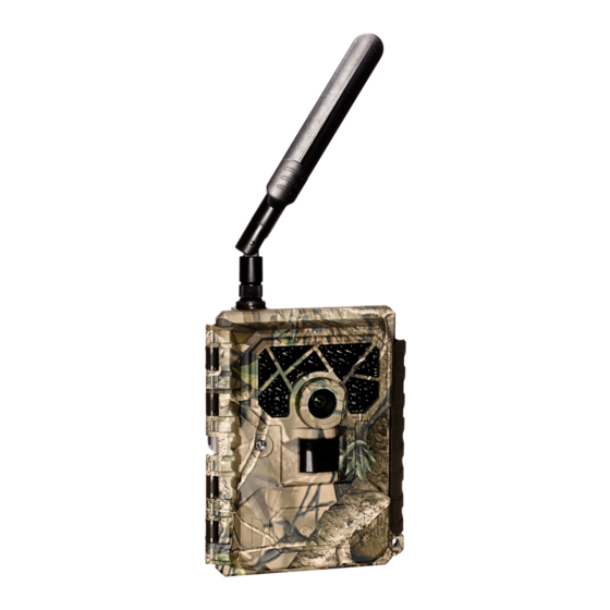
1 Camera Overview 1: Black vision IR flash 2: Lens 3: Light sensor 4: Power switch 5: PIR sensor 6: Key board 7: HD TFT screen 8: LTE main antenna Fig 1 Operation Interface Page 1... -
Page 5: Quick Start Guide
2 Quick start guide 2.1 Installing the batteries This camera can function on 12AA batteries. Pay attention to the (+) or (-) molded into each sleeve to determine if you insert the positive or negative end into the sleeve first. Negative battery terminal always contacts the spring. -
Page 6: Insert The Sim Card
2.3 Insert the SIM card This product support B1/B3/B5/B7/B8/B20@FDD LTE B38/B40/B41@TDD LTE B1/B5/B8@WCDMA B3/B8@GSM. Be sure the PIN code of the SIM card is disabled, and there is enough money in the SIM card. 2.4 Downloading the Mobile App Search“Linckeazi”in your Google Play Store or Apple Store Accessing the Web Portal: Open your web browser to:... -
Page 7: Power Switch And Buttons
Android APP IOS APP 2.5 Power switch and buttons Slide the power switch to SETUP position, then you can start setting the CAM as your favor. Fig2 Power switch Power Switch: OFF: Power off (Please remove batteries when not in use);... - Page 8 Buttons: MENU: Enter menu ▲▼◄►: Navigation button. OK: Confirm operation /Playback photos or video clips. ►: To manually take photo or video. (Click again to stop the video.). Page 5...
-
Page 9: Setting Map
2.6 Setting map Fig3 Main Screen Settings: Page 6... - Page 10 Send Mode: Off: Disable the transmission function. Instant: Enable the instant transmission. Max Number of Instant means the number of photos that is allowed to send out per day. If you want to control your data flow, set the maximum number. The number 00 means infinity.
- Page 11 wireless module is keeping work so the power consumption is huge. Delay 24H means the wireless module will wake up at least one time in 24 hours. Page 8...
- Page 12 Photo Burst:It’s the taken number of pictures when a triggering. If photo burst is 3, it means the camera will take 3 pictures after one triggering. You also can choose which one of the pictures will be sent via Send Option.
- Page 13 PIR Interval: It means how often the PIR sensor can be allowed to work. This prevents the card from filling up with too many redundant images. Time Lapse:When choose time lapse, camera takes photos or videos even when it is not triggered by a nearby live animal.
- Page 14 Password:Make sure you write down your password or save it to your mobile phone so you can access your camera if you ever forget your password. Page 11...
-
Page 15: Send A Test Photo
2.7 Send a test photo 1) Switch camera to Setup mode, press ► button to take a picture, then press OK button to check this picture; 2) Press the MENU button, choose send. You will see sending progress shows on the LCD screen. Fig 4 Fig 5 Once you see send successful, check your email account... -
Page 16: Connecting Cam To Cloud Server
Fig 6 Fig 7 3 Connecting CAM to cloud server 3.1 Connecting CAM to cloud server Open your browser and access the address: https://www.linckeazi.com/index.html Click ‘Sign up’ on the page to pop up the registration page. The registered users of the platform need to fill in the user name, email address, email verification code, setup password, verification password (re-enter the setup password), and then agree to the terms and... - Page 17 Fig 8 Fig 9 Click ‘Add Device’, a form will pop out requesting basic information for your CAM. Page 14...
- Page 18 Fig 10 Fig 11 Name your CAM, and add location description if necessary, the SN and IMEI can be found labeled inside CAM: SN labeled at the side of SIM slit Page 15...
-
Page 19: Send A Photo To Cloud Server
IMEI labeled at the front panel 3.2 Send a photo to cloud server Choose a picture, press MENU, Select ‘send’, the process of sending photo will present at screen, and within minutes your cloud account will receive your photos. If you have the E-mail transfer function enabled on your Linckeazi cloud platform, the cloud platform will also send a photo or video copy to your E-mail address. -
Page 20: Setting Cam With Web Portal Or App
If the above test has accomplished, then you can slide power switch to ‘on’ and start using it take photo or video automatically. 3.3 Setting CAM with Web Portal or APP The CAM can be set up conveniently with cloud server and APP as well. - Page 21 In Google play (or scan the QR code) and install the APK file to your smart phone. Android APP IOS APP The adding and setting process is quite similar to cloud server. Page 18...
-
Page 22: Auxiliary Power
Fig 14 4 Auxiliary power Your camera comes with an Auxiliary power jack. If you want to hook up an external 6V battery to power the camera, you can. The jack necessary to make the connection is a standard 4mm jack. Mount tips For best results, mount the camera approximately Page 19... - Page 23 1-1.5 meter off the ground and 3-15 meters. To enhance the flash, we recommend positioning the camera in an area with a backdrop to reflect the maximum amount of light. Note: a. The sun should not be shining directly on the face of the camera.
- Page 24 c. Avoid placing the camera where the air flow is surging or too much vegetation. False triggers most occur on sunny, breezy days. When the wind moves the vegetation, the camera detects this and cannot distinguish it from a warm-blooded animal moving through the scene.
-
Page 25: Appendixⅰ: Technical Specifications
AppendixⅠ: Technical Specifications Picture Resolution 3/5/8/12/16/20MP Lens F/NO=2.2 FOV (Field of View)=58° (FOV10m=7.72meter) FDD-LTE: Frequency Bands: B1/B3/B5/B7/B8/B20;TDD-LTE:B38/B40/B41 ;WCDMA: B1/B5/B8; GSM: 900/1800 Flash Power Full, Low Display Screen 2.0” LCD Memory Card Up to 32GB Video Resolution 1080P, 720P, WVGA PIR Sensor Multi Zone PIR Sensitivity Adjustable (High/Normal/Low) Trigger Time 0.6s Weight 474g (with... - Page 26 Trigger Interval 0s – 60 min. Time lapse: 3min-24hours Photo Burst 1–10 Video Length 1–60s Power Supply 4AA, 8AA or 12AA Stand-by Current < 0.25 (<6mAh/Day) Power Consumption 12AA batteries can transmit 3000+ Photos Low Battery Alert LED Indicator,Cloud Platform Mounting Rope/Belt/Python lock Dimensions 140mmX95mmX57mm Operation Humidity 5% - 90%...
-
Page 27: Appendix Ⅱ: Parts List
Appendix Ⅱ: Parts List Part Name Quantity Digital Camera Antenna Belt User Manual Quick Start Page 24... - Page 28 Declaration of Conformity to Directive 2014/53/EU CE Caution: Hereby, the manufacturer declares that this camera is in compliance with the essential requirements and other relevant provisions of Directive 2014/53/EU. Please ask for your distributor for a copy of the Declaration of Conformity to Directive 2014/53/EU. Page 25...
- Page 29 Customer Name: Contact Tel: Date of Purchase: Series No: Fault Description: Retailer: The camera manufacturer provides 12 months of warranty service this product against manufacturing defects or malfunctions. If your camera fails to function under normal use within 2 years, the camera manufacturer will repair or replace the camera at no charge.
- Page 30 covered by this warranty. The camera manufacturer can provide repair service, after the warranty expiration. The customer will be responsible for any charges on parts, labor and shipping costs. Please contact the manufacturer for more details. Please contact the area dealer for more details.
Need help?
Do you have a question about the GLORY LTE and is the answer not in the manual?
Questions and answers
When I send a photo to the cloud it gives me a error 41 code. What do I do wrong?