Table of Contents
Advertisement
Quick Links
Advertisement
Table of Contents

Subscribe to Our Youtube Channel
Related Manuals for Skope OD400-2


Summary of Contents for Skope OD400-2
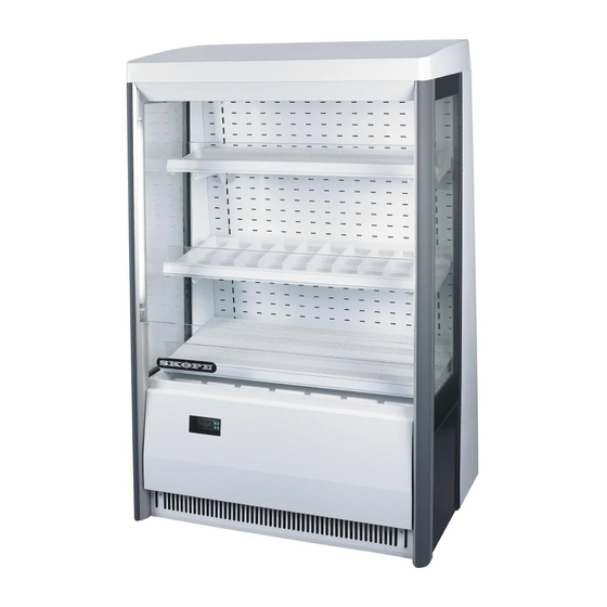
- Page 1 OD400‐2 SKOPE Open Deck Chiller...
- Page 2 E-mail: enquiry@skope.com Website: www.skope.com Trademark Infringement The SKOPE trademark on this product is infringed if the owner, for the time being, does any of the following: • Applies the trade mark to the product after their state, condition, get-up or packaging has been altered in any manner •...
-
Page 3: Table Of Contents
OD400-2 (O43CV) ........ - Page 4 Cabinet ........... . . 58 SKOPE OD400‐2...
-
Page 5: Specifications
SKOPE OD400‐2 Specifications Models This service manual is applicable to the SKOPE chillers detailed below. The type is used to distinguish between different models throughout this manual. Model Description Type OD400-2 2 × interior lights O43CV The chiller may be fitted with refrigeration unit UB84AMD (with Carel ir33 electronic controller) or UB84ANF (with Carel S4 Evo electronic controller). -
Page 6: Electronic Controller
The electronic controller is located behind the front panel and is connected to the refrigeration unit junction box. Customised SKOPE controllers cannot be replaced with standard CAREL controllers. SKOPE Carel ir33 electronic controller Carel S4 Evo electronic controller... -
Page 7: Skope Carel Ir33 Electronic Controller
SKOPE OD400‐2 SKOPE Carel ir33 Electronic Controller Display Item Icon Function Mute / program: Mutes the audible alarm (buzzer) and deactivates the alarm relay. To initiate program sets, press for 5 seconds. Up: To scroll settings up (in program mode). -
Page 8: Cycles
SKOPE OD400‐2 Cycles Defrost Cycle To ensure efficient operation, the electronic controller forces a defrost cycle when required. During a defrost cycle, the compressor stops, DEF and the will display on the electronic controller faceplate. The chiller will resume normal operation once the defrost cycle has finished. A manual defrost can also be initiated by pressing and holding the button. - Page 9 SKOPE OD400‐2 Evaporator Probe The evaporator probe measures the evaporator coil temperature and stops the defrost cycle once the evaporator coil reaches a set temperature. Temperature Probe Reading The temperature of each of the three temperature probes can be displayed...
-
Page 10: Alarms
SKOPE OD400‐2 Alarms The following table explains messages that the electronic controller displays and related alarms. Alarms signal unexpected operational changes in the chiller and stop when action is taken to resolve the problem. Controller alarms Code Display LCD Buzzer... -
Page 11: Hardware Setup
Parameter ‘Ac’ (SKOPE default) = 60 (Shutdown = 60°C) • Parameter ‘AE’ (SKOPE default) = 10 (Warning Initiation = Ac minus AE/2 = 55°C. Warning Reset = Ac minus AE = 50°C). Note: In low ambient conditions the alarm may not activate due to a blocked condenser. -
Page 12: Programming
SKOPE OD400‐2 Programming Set-Point The cabinet is manufactured with a pre-set control temperature set-point. If this set-point does not match your required storage temperature it is recommended that you change the set-point accordingly. The set-point can be adjusted between a temperature range as detailed in the parameter sets beginning on page 17. - Page 13 SKOPE OD400‐2 Controller Reset To delete program modifications and reset the controller to SKOPE default program, or when a replacement controller is being fitted, a ‘Controller Reset’ must be performed. To reset the controller 1. Disconnect the chiller from the power supply.
- Page 14 General Compressor HACCP Defrost Real time clock Alarm Changes to SKOPE factory default programs are not recommended. To access Type C parameters 1. Press the key and keys together for more than 5 seconds. The display will show either ‘00’ or ‘- 1’, representing the password...
- Page 15 SKOPE OD400‐2 3. Scroll the menu with keys. The display shows the codes of the various categories of parameters. 4. When having reached the desired category, press the key to move directly to the first parameter in the category. 5. At this stage, continue to scroll the...
- Page 16 Display Stability To slow down rapid fluctuations and more closely represent actual product temperature, change the probe parameters as detailed below. To change the display stability, adjust parameter ‘/3’ (SKOPE default moderate stabilisation = 8). Electronic Controller...
-
Page 17: Parameters
Default Program Configuration Factory Default Configuration of the controller is set by SKOPE to a specific SKOPE Product. The factory default cannot be altered in the field. A label on the controller box indicates the default program configuration number (e.g. - Page 18 SKOPE OD400‐2 Program 405 - CAREL ir33 (ELZ3333) Electronic Controller Parameter Sheet Revision No. OD400-2 Application SKOPE ir33 Custom Controller Controller Type Perishable Mode IRSKC0HF325 Rev 0.343 Controller Code SKOPE Part Number ELZ3333AP-405 CPS1008-405-BN1 Available parameter sets for this program:...
- Page 19 3. Only make program modifications with reference to relevant Operating Manual. 4. This programming sheet is set exclusively for SKOPE Refrigeration Systems with its dedicated Carel IR33 controller. 5. Any alteration from this program may adversely affect the SKOPE Refrigeration System operation.
-
Page 20: Skope Carel S4 Evo Electronic Controller
SKOPE OD400‐2 SKOPE Carel S4 Evo Electronic Controller Display Because the electronic controller plays such an important role, it’s helpful to know the parts of the faceplate you may use. Item Description Digital display of cabinet temperature or messages. The temperature is what the sensor inside the chiller detects, and not necessarily the product temperature. -
Page 21: Running The Chiller
SKOPE OD400‐2 Running the Operating Modes Chiller The electronic controller runs the chiller in constant ‘Normal’ mode. The OD400-4 does not use an energy saving/night mode (or similar). Note: Normal mode is suitable for perishable product (all shelves maintain temperature below 5°C). -
Page 22: Messages And Alarms
SKOPE OD400‐2 Messages and Controller Display Alarms The following table explains messages and alarms that the electronic controller displays. Alarms signal unexpected operational changes in the chiller and can be muted by pressing the set (mute) button on the electronic controller faceplate (see page 20). -
Page 23: Hardware Setup
SKOPE OD400‐2 Cold Climate Protection The chiller will enter cold climate protection (CCP) mode if the ambient temperature becomes too cold. This happens if the control probe (at the evaporator air out) detects the interior temperature below -0.3°C (parameter St - CCt) for more than 30 minutes (parameter CCd). The lights will stay on and cannot be switched off while the chiller is in CCP mode. -
Page 24: Programming The Electronic Controller
0°C and 3.5°C if required (see over page). SKOPE do not recommend that the setpoint be changed unless it is absolutely necessary, and then only by small increments at a time. To view and adjust the temperature setpoint 1. - Page 25 SKOPE OD400‐2 Category Initial Icon Probe parameters Control parameters Compressor parameters Defrost parameters Alarm parameters Fan parameters 6. Press the Set (mute) button to display the value associated with the parameter code. 7. Use the ES (up) and Light (down) buttons to increase or decrease the value of the parameter.
- Page 26 SKOPE OD400‐2 Program 108 - OD400-2 Electronic Controller Parameter Sheet Revision: OD400-2 Full List Application SKOPE S4 EVO Controller Type SET0 PZSKC0H002K (Rev 1.414) Controller Model & Revision ELZ11478-108 CPS1017-108-SET0 SKOPE Part Number Last revised on 16-Feb-2018 Parameter Setting Unit...
- Page 27 1. Only make program modifications with reference to relevant Operating Manual. 2. This programming sheet is exclusively for SKOPE refrigeration systems with its dedicated Carel controller. 3. Any alteration from this program may adversely affect the SKOPE Refrigeration System operation.
-
Page 28: Wiring
SKOPE OD400‐2 Wiring Model: OD400‐2 with UB84AMD (Carel ir33 electronic controller) GNYE GNYE Isolation Isolation Switch Switch EMC Filter EMC Filter T1-1 T1-1 T1-3 T1-3 S1-L P1-L S1-L P1-L S1-N P1-N S1-N P1-N & 2 & 2 & 4 & 4... -
Page 29: Model: Od400-2 With Ub84Anf (Carel S4 Evo Electronic Controller)
SKOPE OD400‐2 Model: OD400‐2 with UB84ANF (Carel S4 Evo electronic controller) GNYE EMC Filter T1-4 T1-2 P7-N S7-N GNYE S7-L P7-L & 5 & 3 P7-E S7-E GNYE Fuse Condenser Controller Motor Compressor Overload Comp. T1-7 Relay Control Start Capacitor... -
Page 30: Spare Parts
SKOPE OD400‐2 Spare Parts Cabinet Assembly ‐ OD400‐2 (O43CV) Spare Parts Service Manual... - Page 31 10 Middle shelf RH height adjustment bracket (no hooks) O290/598CR 11 Middle shelf RH bracket (with hooks) STY10378R 12 Bottom shelf O403/589 13 Gravity shelf matting (set for 3 × OD400-2 shelves) SXX11216 14 Ticket strip PLE2470-0815 15 Side window...
-
Page 32: Electrics Plate Assembly
SKOPE OD400‐2 Electrics Plate Assembly Parts — Electrics Plate Assembly Item Description SKOPE Part No. Customer Part No. Electrics plate assembly - two light config. O460/G29L Electrics plate assembly - three light config. O461/G29L IEC socket outlet ELK8880 2-Pole rocker switch... -
Page 33: Evaporator Fan Deck Assembly
SKOPE OD400‐2 Evaporator Fan Deck Assembly Parts — Evaporator Fan Deck Item Description SKOPE Part No. Customer Part No. Evaporator fan deck assembly O403/R39 Evaporator fan motor ELM7230 Terminal box O460/E92 Wire fan guard WRK11151 Spare Parts Service Manual... -
Page 34: Unit Junction Box Assembly (Carel Ir33)
SKOPE Part No. Customer Part No. Unit junction box assembly UB84AMD/R86 ENSTO 5-Pole socket ELZ0499-5 ENSTO 5-Pole panel adaptor PLM0497-5 SKOPE CAREL IR33 electronic controller (OD400 ELZ3333AP-405 program 405) 3A ceramic fuse ELZ9654 Fused terminal block ELZ9655 Unit junction box base... -
Page 35: Unit Junction Box Assembly (Carel S4 Evo)
SKOPE OD400‐2 Unit Junction Box Assembly (Carel S4 Evo) Parts — Unit Junction Box Item Description SKOPE Part No. Customer Part No. Unit junction box assembly UB84ANF/R86-108 ENSTO 5-Pole socket ELZ0499-5 ENSTO 5-Pole panel adaptor PLM0497-5 CAREL S4 Evo electronic controller (program 108) -
Page 36: Refrigeration Unit Assembly (Carel Ir33)
SKOPE OD400‐2 Refrigeration Unit Assembly (Carel ir33) Parts — Refrigeration Unit Item Description SKOPE Part No. Customer Part No. Refrigeration unit assembly UB84AMD Compressor Embraco NEK6212Z CPR10543 Drier DRY8783 Condenser coil CLS11034 Condenser fan motor UB83AAD/404CP1 Condenser fan blade FAN3809... -
Page 37: Refrigeration Unit Assembly (Carel S4 Evo)
SKOPE OD400‐2 Refrigeration Unit Assembly (Carel S4 Evo) Parts — Refrigeration Unit Item Description SKOPE Part No. Customer Part No. Refrigeration unit assembly UB84ANF-108IE Compressor Embraco NEK6212Z CPR10543 Drier DRY8783 Condenser coil CLS11034 Condenser fan motor UB83AAD/404CP1 Condenser fan blade... -
Page 38: Installation
SKOPE OD400‐2 Installation Climate Class The chiller is designed to operate within a climate class 3 environment (25°C @ 60% RH). We recommend that you put the chiller in the coolest place possible because it will use less power and last longer. - Page 39 SKOPE OD400‐2 60mm 60mm 100mm 500mm Front Exhaust air Exhaust air Back wall intake Free-standing installation ventilation requirements 100mm Enclosed installations Enclosed installations must have the following minimum clearances around the cabinet, and include the following features: 75mm behind the cabinet.
-
Page 40: Shelves
SKOPE OD400‐2 Shelves Installing the The chiller is supplied with three metal shelves. The shelves are different Shelves depths, with the top shelf being the shallowest and the bottom shelf the deepest. The bottom shelf is fixed in position, and the two top shelves are height and angle adjustable, and removable. -
Page 41: Optional Gravity Shelf System
SKOPE OD400‐2 Optional When the chiller is ordered with the optional gravity feed matting, each shelf Gravity Shelf is supplied with corresponding gravity feed matting and shelf dividers. The gravity shelf system comes in three sizes to suit the three different size System shelves. -
Page 42: Replacement Procedures
SKOPE OD400‐2 Replacement Procedures Isolating Electrics The chiller should be isolated from the power supply before attempting any maintenance. Use the isolating switch and plug, located in the refrigeration unit compartment, to turn off the electrics to the cabinet and refrigeration unit without unplugging the cabinet from the wall. -
Page 43: Lighting
SKOPE OD400‐2 Lighting The chiller is fitted with two LED side lights powered by a 24V 25W LED driver power supply. The cabinet interior lights will switch on when the cabinet is plugged in, and will stay on permanently while the cabinet is connected to the power supply. -
Page 44: Cabinet Electrics
SKOPE OD400‐2 Cabinet Electrics Electrics Plate The cabinet is fitted with an electrics plate assembly, located on the LH side Assembly of the refrigeration unit conpartment. The electrics plate assembly houses the cabinet electrical components including the lights power supply, the surge protector/EMI filter, isolation switch, and the mains IEC connector socket. - Page 45 SKOPE OD400‐2 when the chiller is connected to the power supply and the isolation switch is Replacement Procedures Service Manual...
-
Page 46: Front Upstand
SKOPE OD400‐2 Front Upstand The front upstand is located at the bottom of the cabinet opening. The front upstand must be in place at all time as it directs the air curtain. To replace the front upstand 1. Remove the front panel and isolate the chiller from the mains power supply (see page 42). -
Page 47: Evaporator Fan Assembly
SKOPE OD400‐2 Evaporator The evaporator fan assembly is located under the fixed bottom shelf, and is Fan Assembly made up of two fans, two fan guards, a terminal block and a mounting plate. Each fan motor has a push in plug for easy removal and replacement. -
Page 48: Refrigeration Unit
SKOPE OD400‐2 Refrigeration Unit Introduction The SKOPE OD400-2 refrigeration unit is a bottom mounted, electronically controlled, removable cassette. For major servicing the refrigeration unit unplugs and pulls out from the cabinet (see page 49). Minor servicing can be performed without removing the refrigeration unit from the cabinet. -
Page 49: Removing The Refrigeration Unit
SKOPE OD400‐2 Removing the To remove the refrigeration unit Refrigeration 1. Remove the front kick panel and isolate the chiller from the power supply (see Unit page 42). 2. Remove the top screw from each lifting arm and pull both arms Cabinet supply down. -
Page 50: Condenser Fan
SKOPE OD400‐2 Condenser The condenser fan assembly is made up of a fan blade, a motor and a bracket. The motor is attached to the bracket fixed onto the condenser coil shroud. When viewed from the inside of the refrigeration unit (motor end), the motor and blade should rotate in a clockwise direction and pull air through the front of the refrigeration unit. -
Page 51: Compressor
SKOPE OD400‐2 Compressor The compressor is located at the front of the refrigeration unit behind the compressor cover. Before replacing the compressor, ensure the compressor electrics are operating correctly and that the compressor is being supplied with consistent voltage over 220 Volts. Ensure the voltage does not drop at start- up. -
Page 52: Evaporator Coil
SKOPE OD400‐2 Evaporator The evaporator coil is located inside the evaporator box and can be lifted up Coil for servicing. To lift up the evaporator coil 1. Remove the front kick panel and isolate the chiller from the power supply (see page 42). -
Page 53: Condenser Coil
SKOPE OD400‐2 Condenser The condenser coil is located at the front of the refrigeration unit beside the Coil compressor. To access the condenser coil 1. Remove the front kick panel and isolate the chiller from the power supply (see page 42). -
Page 54: Electronic Controller
SKOPE OD400‐2 Electronic Controller Introduction The electronic controller is located inside the unit junction box (see page 49). For information on operating and programming the controller, see page 6. Removal To access and remove the electronic controller 1. Remove the front kick panel and isolate the chiller from the power supply (see page 42). -
Page 55: Temperature Probes
SKOPE OD400‐2 Temperature The electronic controller uses three temperature probes to gather data from Probes the refrigeration unit: the control, evaporator and condenser probes. The probes connect into the rear of the electronic controller and exit from the rear of the unit junction box to their locations. - Page 56 SKOPE OD400‐2 Condenser Probe The condenser probe determines refrigeration shutdown due to overheating of condensing temperature. The condenser probe is located and insulated on outside middle tube of condenser. To access the condenser probe 1. Remove the front kick panel and isolate the chiller from the power supply (see page 42).
-
Page 57: Cleaning
SKOPE OD400‐2 Cleaning Ensure the cabinet is disconnected from the mains power supply before cleaning the cabinet. Cabinet When necessary, wipe both the interior and exterior of the cabinet with a damp cloth. The bottom shelf can be removed to assist with cleaning by undoing the two side fixing screws. -
Page 58: Troubleshooting
SKOPE OD400‐2 Troubleshooting Cabinet The following ‘Troubleshooting’ guide should be used as a supplement to standard refrigeration fault finding principles. Complaint Possible Cause Repair 1. Cabinet warm, • External drafts, possibly from air- • Confirm visually any potential conditioning, door ways or ventilation airflow draft outlets. - Page 59 SKOPE OD400‐2 7. Pressure Switch • Restricted ventilation. • Ensure no restriction to cabinet airflow at front and rear of cabinet. If activated possible, space the cabinet slightly - controller displays out from the wall. ‘cht’ and ‘CHT’ • Excessive heatload into cabinet.
- Page 60 SKOPE Industries Limited NEW ZEALAND CONTACT Head Office PO Box 1091, Christchurch New Zealand Freephone: 0800 947 5673 Fax: (03) 983 3896 E-mail: enquiry@skope.com Website: www.skope.com AUSTRALIAN CONTACT A.B.N. 73 374 418 306 PO Box 7543, Baulkham Hills B.C. NSW 2153, Australia...
Need help?
Do you have a question about the OD400-2 and is the answer not in the manual?
Questions and answers