Table of Contents
Advertisement
Quick Links
Advertisement
Table of Contents

Subscribe to Our Youtube Channel
Related Manuals for Skope OD260


Summary of Contents for Skope OD260
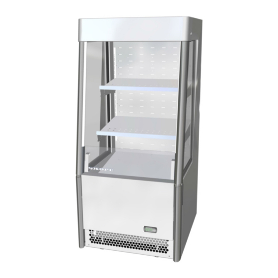
- Page 1 OD260 SKOPE Open Deck Chiller...
- Page 2 E-mail: enquiry@skope.com Website: www.skope.com Trademark Infringement The SKOPE trademark on this product is infringed if the owner, for the time being, does any of the following: • Applies the trade mark to the product after their state, condition, get-up or packaging has been altered in any manner •...
-
Page 3: Table Of Contents
Model: OD260 ........ - Page 4 Condenser Coil ........40 Troubleshooting SKOPE OD260 Service Manual...
-
Page 5: Specifications
SKOPE OD260 Specifications Models This service manual is applicable to the SKOPE chillers detailed below. The type is used to distinguish between different models throughout this manual. Model Description Type OD260 2 × interior lights O26CY OD260 Cabinet Description Open Deck Chiller... -
Page 6: Electronic Controller
The electronic controller controls and displays the chiller temperature, and signals temperature alarms. To ensure efficient operation, the electronic controller automatically forces a defrost cycle when required. The electronic controller is pre-programmed. SKOPE does not recommend that settings be changed unless it is absolutely necessary. Electronic Controller Service Manual... -
Page 7: Faceplate
SKOPE OD260 Faceplate Because the electronic controller plays such an important role, it’s helpful to know the parts of the faceplate you may use. Item Description Digital display of cabinet temperature or messages. The temperature is what the sensor inside the chiller detects, and not necessarily the product temperature. -
Page 8: Running The Chiller
Operating The electronic controller runs the chiller in constant ‘Normal’ mode. The Modes OD260 does not use an energy saving/night mode (or similar). Note: Normal mode is suitable for perishable product (all shelves maintain temperature below 5°C). During some conditions or refrigeration system alarms, the electronic controller may run the chiller in cold climate protection mode, or may shut down the lights and/or refrigeration system. -
Page 9: Messages And Alarms
SKOPE OD260 Messages and Alarms Controller The following table explains messages and alarms that the electronic Display controller displays. Alarms signal unexpected operational changes in the chiller and can be muted by pressing the set (mute) button on the electronic controller faceplate (see page 7). -
Page 10: Cold Climate Protection
SKOPE OD260 Cold Climate The chiller will enter cold climate protection (CCP) mode if the ambient Protection temperature becomes too cold. This happens if the control probe (at the evaporator air out) detects the interior temperature below -0.3°C (parameter St - CCt) for more than 30 minutes (parameter CCd). The lights will stay on and cannot be switched off while the chiller is in CCP mode. -
Page 11: Hardware Setup
SKOPE OD260 Hardware Setup Hardware The controller has three hardware inputs as detailed in the table below. All Inputs use pin 9 as common. Electronic controller hardware inputs Pins (on rear of Hardware description controller) Control probe 9-10 Condenser probe... -
Page 12: Programming The Electronic Controller
0°C and 4°C if required (see over page). SKOPE do not recommend that the setpoint be changed unless it is absolutely necessary, and then only by small increments at a time. To view and adjust the temperature setpoint 1. -
Page 13: Parameter History
SKOPE OD260 Category Initial Icon Probe parameters Control parameters Compressor parameters Defrost parameters Alarm parameters Fan parameters 6. Press the Set (mute) button to display the value associated with the parameter code. 7. Use the ES (up) and Light (down) buttons to increase or decrease the value of the parameter. - Page 14 SKOPE OD260 Parameter list - Program 107 - OD260 (page 1 of 2) Electronic Controller Parameter Sheet Revision: OD260 Full List Application SKOPE S4 EVO Controller Type SET0 PZSKC0H002K (Rev 1.414) Controller Model & Revision ELZ11478-107 CPS1017-107-SET0 SKOPE Part Number...
- Page 15 1. Only make program modifications with reference to relevant Operating Manual. 2. This programming sheet is exclusively for SKOPE refrigeration systems with its dedicated Carel controller. 3. Any alteration from this program may adversely affect the SKOPE Refrigeration System operation.
-
Page 16: Wiring
SKOPE OD260 Wiring Model: OD260 GNYE GNYE EMC Filter P1-N S1-N S1-L P1-L T1-1 & 2 T1-3 & 4 P4-4 S4 EVO Comp. S4-2 P4-2 S4-1 P4-1 S7-2 P-2 Condenser Lights Compressor Overload Cabinet S7-1 P7-1 T6-1 Probe S8-1 P8-1... -
Page 17: Notes
SKOPE OD260 Notes Wiring Service Manual... -
Page 18: Spare Parts
SKOPE OD260 Spare Parts Cabinet Assembly ‐ OD260 10 12 15 14 Spare Parts Service Manual... - Page 19 SKOPE OD260 Parts — Cabinet OD260 Item Description SKOPE Part No. Standard White Black Plastic lid PLM1662A-WH PLM1662A-BK Plastic lid screw PLM10437WH PLM10437BK Top shelf O260/591C-32 O260/591C-49 Top shelf bracket - one part version* STY11671-32 STY11671-49 Top shelf bracket LH - two part...
-
Page 20: Electrics Plate Assembly
SKOPE OD260 Electrics Plate Assembly Parts — Electrics Plate Assembly Item Description SKOPE Part No. Electrics plate assembly O260/G29 EMI filter ELZ10136 Light power supply O260/K08 3A fuse ELZ9654 Fuse holder ELZ9655 Spare Parts Service Manual... -
Page 21: Unit Electrics Box Assembly
SKOPE OD260 Unit Electrics Box Assembly Parts — Unit Junction Box Item Description SKOPE Part No. Unit junction box assembly UB89ABF/R86-107 Controller faceplate UB89ABF/K03/1-49 CAREL S4 Evo electronic controller (program 107) ELZ11478-107 TYCO 4-Pole socket red ELZ11345-RD TYCO 2-Pole socket red... -
Page 22: Refrigeration Unit Assembly
SKOPE OD260 Refrigeration Unit Assembly Spare Parts Service Manual... - Page 23 SKOPE OD260 Parts — Refrigeration Unit Item Description SKOPE Part No. Refrigeration unit assembly UB84ABF-107IE Condenser coil CLS10627 Condenser fan shroud UB89AA/232-49 Condenser fan blade FAN3809 Condenser fan motor UB89ABF/404CP1 Compressor Embraco NEK6210Z CPR10608 Condensate line assembly UB89ABF/255T-99 Drier DRY6110...
-
Page 24: Installation
SKOPE OD260 Installation Climate Class The chiller is designed to operate within a climate class 3 environment (25°C @ 60% RH). We recommend that you put the chiller in the coolest place possible because it will use less power and last longer. - Page 25 SKOPE OD260 60mm 60mm 100mm 500mm Front Exhaust air Exhaust air Back wall intake Free-standing installation ventilation requirements 100mm Enclosed installations Enclosed installations must have the following minimum clearances around the cabinet, and include the following features: 75mm behind the cabinet.
-
Page 26: Stabiliser Feet
SKOPE OD260 Stabiliser Feet Ensure the stabiliser feet are wound all the way up when moving the chiller around. Once the chiller is in position, wind down the two front stabiliser feet to firmly contact the ground. Front panel Stabiliser foot... -
Page 27: Shelves
SKOPE OD260 Shelves Installing the The chiller is supplied with three metal shelves. The shelves are different Shelves depths, with the top shelf being the shallowest and the bottom shelf the deepest. The bottom shelf is angled and fixed in position. The two top shelves are height and angle adjustable, and removable. -
Page 28: Replacement Procedures
SKOPE OD260 Replacement Procedures Isolating Electrics The chiller should be isolated from the power supply before attempting any maintenance. Unplug the cabinet from the power supply to isolate. Replacement Procedures Service Manual... -
Page 29: Lighting
SKOPE OD260 Lighting The chiller is fitted with two LED side lights powered by a 24V 25W LED driver power supply. The cabinet interior lights will switch on when the cabinet is plugged in, and can be switched on and off with the light switch on the electronic controller faceplate. -
Page 30: Cabinet Electrics
SKOPE OD260 Cabinet Electrics Electrics Plate The cabinet is fitted with an electrics plate assembly, located on the RH side Assembly of the cabinet. The electrics plate assembly houses cabinet electrical components including the lights power supply, the surge protector/EMI filter, and the mains IEC connector socket. -
Page 31: Front Upstand
SKOPE OD260 Front Upstand The front upstand is located at the bottom of the cabinet opening. The front upstand must be in place at all time as it directs the air curtain. To replace the front upstand 1. Isolate the chiller from the mains power supply. -
Page 32: Refrigeration Unit
SKOPE OD260 Refrigeration Unit Introduction The refrigeration unit is a bottom mounted, electronically controlled, removable cassette. For major servicing the refrigeration unit unplugs and pulls out from the cabinet (see page 33). Minor servicing can be performed without removing the refrigeration unit from the cabinet. -
Page 33: Removing The Refrigeration Unit
SKOPE OD260 Removing the To remove the refrigeration unit Refrigeration 1. Disconnect the cabinet from the power supply. Unit 2. Remove the front panel. Take care not to scratch the front upstand when removing. Control probe (blue) 3. Unplug the IEC plug from the... -
Page 34: Unit Junction Box
SKOPE OD260 Unit Junction The refrigeration unit connectors and electronic controller are located inside the unit junction box. The box is mounted to the front of the refrigeration unit. The interior can be accessed without removing the refrigeration unit, however this will only offer restricted access to components. -
Page 35: Evaporator Fans
SKOPE OD260 Evaporator The refrigeration unit is fitted with two evaporator fans, attached to the Fans evaporator fan shroud on top of the unit. The fans can be replaced individually and each fan has a push in plug for easy removal. -
Page 36: Electronic Controller
SKOPE OD260 Electronic Controller Introduction The electronic controller is located inside the unit junction box (see page 34). For information on operating and programming the controller, see page 6. Removal To access and remove the electronic controller 1. Isolate the chiller from the power supply. -
Page 37: Temperature Probes
SKOPE OD260 Temperature The electronic controller uses three temperature probes to gather data from Probes the refrigeration unit: the control, evaporator and condenser probes. The probes connect into the rear of the electronic controller and exit from the rear of the unit junction box to their locations. -
Page 38: Condenser Probe
SKOPE OD260 Condenser The condenser probe is attached to the side of the condenser coil and Probe wrapped with insulating cork tape. The condenser probe cable runs along the floor of the refrigeration unit behind the condenser coil. To replace the condenser probe 1. -
Page 39: Service Probe
SKOPE OD260 To replace the evaporator probe 1. Remove the front panel, isolate the chiller from the mains power supply and remove the refrigeration unit (see page 33). 2. Detach the evaporator fan assembly from the evaporator coil by undoing the four fixing screws (two at each end), and place the evaporator fan assembly out of the way. -
Page 40: Cleaning
SKOPE OD260 Cleaning Ensure the cabinet is disconnected from the mains power supply before cleaning the cabinet. Cabinet When necessary, wipe both the interior and exterior of the cabinet with warm soapy water and a soft cloth. Do not use chemical cleaners. -
Page 41: Troubleshooting
SKOPE OD260 Troubleshooting The following ‘Troubleshooting’ guide should be used as a supplement to standard refrigeration fault finding principles. Complaint Possible Cause Repair 1. Cabinet warm, • External drafts, possibly from air- • Confirm visually any potential conditioning, door ways or ventilation airflow draft outlets. - Page 42 SKOPE OD260 7. Controller displays • Restricted ventilation. • Ensure no restriction to cabinet airflow at front and rear of cabinet. If ‘cht’ and ‘CHT’ possible, space the cabinet slightly alarms out from the wall. • Excessive heatload into cabinet.
- Page 43 SKOPE Industries Limited A.B.N. 73 374 418 306 AU: 1800 121 535 NZ: 0800 947 5673 skope@skope.com www.skope.com...
Need help?
Do you have a question about the OD260 and is the answer not in the manual?
Questions and answers