Table of Contents
Advertisement
Advertisement
Table of Contents
Troubleshooting

Related Manuals for Skope SK650-2


Summary of Contents for Skope SK650-2
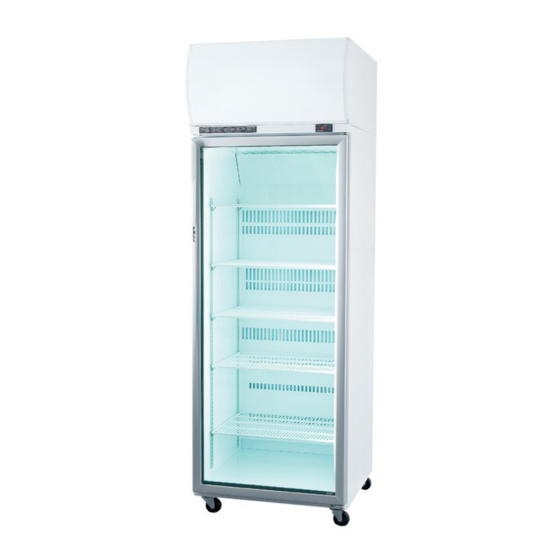
- Page 1 Vertical Display and Storage SK650-2 SKOPE Gen2: Single Door Chiller...
- Page 3 E-mail: enquiry@skope.co.nz Website: www.skope.co.nz Australia SKOPE AUSTRALIA PTY LTD A.C.N. 000 384 270 PO Box 7543, Baulkham Hills B.C. NSW 2153, Australia Freephone: 1800 121 535 Fax: 1800 121 533 E-mail: enquiry@skope.com.au Website: www.skope.com.au SK650-2 SKOPE Gen2: Single Door Chiller...
- Page 4 SK650-2 SKOPE Gen2: Single Door Chiller Operating and Service Manual MAN0516 Rev. 3.0 August 2005 edition. Copyright © 2003 SKOPE Industries Limited. All rights reserved. SKOPE and CYCLONE are registered trademarks of SKOPE Industries Limited. SKOPE Industries Limited reserve the right to alter specifications without notice.
-
Page 5: Table Of Contents
Pressure Temperature Chart ......42 Troubleshooting Chart ......44 SK650-2 SKOPE Gen2: Single Door Chiller... - Page 6 WIRING DIAGRAMS Model: SK650-2 (Type V60BA) ..... 48 Model: SK650-2 (Type V60BB) ..... 50 SPARES Cabinet Assembly .
-
Page 7: Specifications
740mm Depth: 700mm Floor area: 0.52m Internal volume: 610 litres Refrigeration Unit ® SKOPE top mounted integral Cyclone refrigeration unit: Nominal capacity: 581 Watts Compressor: Electrolux GLY90RA Refrigerant: R134a / 450 grams Electrical 230-240 Volts a.c. 50 Hz, single phase power supply Run Amps: 2.77 Amps... -
Page 8: Operation
• Do NOT probe any opening. • Only use this appliance with voltage specified on the rating label. • Ensure adequate ventilation of the SKOPE refrigeration unit. • Be careful not to touch moving parts and hot surfaces. • Regulations require that all electrical work be carried out by authorised persons. -
Page 9: Operation Of Machine
Cabinet lights The lights which illuminate the top sign and cabinet interior are initially on, and will stay on permanently. The lighting will require a period of time to stabilise following initial start up. SK650-2 SKOPE Gen2: Single Door Chiller... -
Page 10: Loading
• do not allow products to overhang the front of the shelf as this could prevent the door from shutting or cause glass breakage. Shelf Support Strip Shelf Shelf Clip ‘+’ Mark Figure 1: Shelf Clip SK650-2 SKOPE Gen2: Single Door Chiller... -
Page 11: Cleaning
3. Lift the sign unit up, to disengage from the sign sides. 4. Disconnect the sign ENSTO plug from the electrical box socket, and remove the sign unit from the cabinet. Caution: Disconnect the cabinet from the mains power supply before cleaning the condenser coil. SK650-2 SKOPE Gen2: Single Door Chiller... -
Page 12: Electronic Controller
Key Combinations: Press both keys simultaneously, to lock and unlock the keypad Press both keys simultaneously, to enter the programming mode Press both keys simultaneously, to return to room temperature display Table 2: Controller Operation SK650-2 SKOPE Gen2: Single Door Chiller... -
Page 13: Controller Operation
The Set Point is displayed Table 3: LED Functions 3.2 Controller Operation The SKOPE electronic controller controls and displays the cabinet temperature. The preset temperature setting controls internal air temperature between 2°C and 4°C. The electronic controller also signals and records temperature alarms, together with their duration and maximum value reached (see Table 5 on page 18). -
Page 14: Programming Controller
LED will start blinking. 3. To change the Set value, push the UP or DOWN keys. 4. To memorise the new Set Point value, push the SET key again or wait 15 seconds. SK650-2 SKOPE Gen2: Single Door Chiller... - Page 15 1. The Set value is stored even when the procedure is exited by waiting for the time-out to expire. 2. Dependent on customer requirements, the SKOPE electronic controller has different parameter configurations. Parameter configuration 160 = Beverage, 170 = Food, and 200 = Set Point display (see ‘Controller Parameters’...
- Page 16 1. Press and hold the SET key for more than 3 seconds, while the maximum or minimum temperature is displayed. The ‘rSt’ message will be displayed. 2. To confirm the operation, the ‘rSt’ message starts flashing and the normal temperature will be displayed. SK650-2 SKOPE Gen2: Single Door Chiller...
-
Page 17: Parameters
0 Mins 23.5 Hours Condenser alarm temperature delay at start up Alarm relay polarity OTHER PARAMETERS °C Thermostat probe read out °C Condenser probe read out Software release Map code Table 4: Controller Parameters SK650-2 SKOPE Gen2: Single Door Chiller... -
Page 18: Alarm Displays
• Condenser alarm ‘CSd’ temperature recovers by replugging the cabinet power supply (or isolation switch). In this case, all the alarms are reset. • Cabinet temperature alarms ‘LO’ and ‘HI’ automatically stop at temperature recovery. SK650-2 SKOPE Gen2: Single Door Chiller... -
Page 19: Replacement
ELECTRONIC CONTROLLER 3.6 Replacement If the SKOPE electronic controller has a suspected fault, care must be taken to ensure accurate diagnosis. The controller has various programmable parameters that effect operation such as time delay and defost modes. Any suspected failure must be double checked. - Page 20 (see Figure 4 below). Housing Lid Controller Cable Probe Cables Cord Grip Parameter Configuration Label Controller Housing Top Fixing Screws Electronic Controller Figure 4: Controller Housing (closed) SK650-2 SKOPE Gen2: Single Door Chiller...
- Page 21 6.3mm Q.C. PCB mount terminals, providing a more reliable connection. This change is effective from February 2005, cabinet serial no. A050212714. Figure 5: Figure 6: Dixell XR30C ELZ0471 Dixell XR30C ELZ0471 Rev B Controller Rev A Controller SK650-2 SKOPE Gen2: Single Door Chiller...
- Page 22 Howev- er, the connections at the refrigeration system electrical junction box remain the same. Figure 8: Figure 7: Dixell XR30C ELZ0471 Dixell XR30C ELZ0471 Rev A Controller Rev B Controller SK650-2 SKOPE Gen2: Single Door Chiller...
-
Page 23: Service Instructions
SERVICE INSTRUCTIONS 4.1 Interior Side Light/s The SK650-2 can have one or two interior side lights. Each side light houses one 35 Watt T5 fluorescent tube, which may be replaced without removing shelves or product from the cabinet. To replace the fluorescent tube: 1. -
Page 24: Door
Should the gasket be out of shape when in place, use hot air (i.e. from hair drier) to realign. Gasket Retainer Door Gasket Door Frame Figure 10: Door Gasket Removal SK650-2 SKOPE Gen2: Single Door Chiller... - Page 25 In the event the door tension can no longer be adjusted, the torsion bar may need replacing (see ‘Torsion bar replacement’, page 26). Bottom Hinge Bracket Door Split Pin Door alignment adjustment screw Ø2.5mm steel rod Capstan Figure 11: Door Tension SK650-2 SKOPE Gen2: Single Door Chiller...
- Page 26 6. Lightly tap bottom of Bush capstan into hinge hole, until the bush is flush with door frame. Capstan 7. Refit the door to cabinet, and adjust tension (see ‘Door tension’, page 25). Figure 12: Torsion Bar Assembly SK650-2 SKOPE Gen2: Single Door Chiller...
- Page 27 4. Refit torsion bar assembly into the opposite end of the door. 5. Refit top door bush. 6. Refit the door to the cabinet (see ‘Door removal’, above). 7. Re-tension the door (see ‘Door tension’ on page 25). SK650-2 SKOPE Gen2: Single Door Chiller...
-
Page 28: Sign Unit
5. The fluorescent tube can now be accessed for replacement (see Figure 15 on page 29). Sign Top Cover Sign Top Cover Corner Notch Corner Notch Sign Panel End Strip Sign Panel Figure 13: Removing Sign Panel Figure 14: Sign Corner Detail SK650-2 SKOPE Gen2: Single Door Chiller... - Page 29 Centre Tie Wire Fluorescent Tube Sign Wiring Cover Sign Top Cover Sign Unit Sign Panel End Strip Sign Panel Sign Bottom Cover Sign ENSTO 3-pole Plug Figure 15: Sign Unit (with sign panel removed) SK650-2 SKOPE Gen2: Single Door Chiller...
- Page 30 7. The electronic ballast, mounted on the back of the sign wiring cover, can now be accessed for replacement (see Figure 16 below). Electronic Ballast Sign Wiring Cover Connector Block Figure 16: Electronic Ballast SK650-2 SKOPE Gen2: Single Door Chiller...
- Page 31 Unit Junction Box Sign ENSTO Plug Sign Side Panel Sign Unit Sign Retaining Clip Figure 17: Sign ENSTO Plug Figure 18: Sign Retaining Clip SK650-2 SKOPE Gen2: Single Door Chiller...
- Page 32 7. When refitting the side panels, ensure to refit the sign back panel and to tighten the keyhole screws. Sign Side Panel Keyhole Screw Cabinet Top Sign Back Panel Figure 19: Sign Back Panel Figure 20: Sign Side Fixing SK650-2 SKOPE Gen2: Single Door Chiller...
-
Page 33: Refrigeration Unit
SERVICE INSTRUCTIONS 4.4 Refrigeration Unit The SKOPE Cyclone® unit is a self-contained refrigeration module, which aligns with port holes in the roof of the cabinet. Air is drawn through the evaporator and blown down the back duct. Air returns to the evaporator through the roof port hole. - Page 34 Evaporator Box Compressor Condenser Fan Motor Condenser Coil Unit Retaining Bracket Unit Handle Unit Base Electronic Controller Mains Supply Unit Junction Box Flex Cabinet and Sign Supply Sockets Figure 21: Refrigeration Unit SK650-2 SKOPE Gen2: Single Door Chiller...
- Page 35 4. Ensure the unit junction box cover is replaced after servicing. ENSTO 3-Way Socket Junction Box Base ENSTO 3-Way Fan Motor Capacitor Panel Adaptor 3 Amp Fuse Cover Earth Wire Fan Motor Flexes Mains Flex Figure 22: Unit Junction Box (with cover removed) SK650-2 SKOPE Gen2: Single Door Chiller...
- Page 36 9. Replace the fan motor capacitor inside the unit junction box. Fan Blade Fixing Screws (2) Clamp Condenser Fan Motor Assembly Liquid / Drier Line Condenser Fan Motor Condenser Coil Figure 23: Condenser Fan Motor Assembly SK650-2 SKOPE Gen2: Single Door Chiller...
- Page 37 Evaporator Fan Motor Assembly Evaporator Motor Junction Box Evaporator Motor Evaporator Fan Blade Evaporator Motor Flex Fan Motor Capacitor Flex Hole Seal Figure 24: Evaporator Fan Motor Figure 25: Evaporator Motor Assembly Junction Box SK650-2 SKOPE Gen2: Single Door Chiller...
- Page 38 3. Lift the sign unit up, to disengage from the sign sides. 4. Disconnect the sign ENSTO plug from the unit junction box socket, and remove the sign unit from the cabinet. Evaporator Box Condenser Coil Unit Handle Controller Cables Figure 26: Condenser Coil SK650-2 SKOPE Gen2: Single Door Chiller...
- Page 39 SERVICE INSTRUCTIONS Recommended Service Procedures SKOPE recommend the SKOPE Cyclone® demountability and exchangeability philosophy, which in essence means: The customer must not be inconvenienced during system maintenance. In the unlikely event of Refrigeration failure, an exchange unit is simply swapped in a matter of minutes. There is no cabinet down time or unloading product.
- Page 40 Finally, pinch-off the gauge process lines (or remove line piercing valves) and braze the system closed. SKOPE recommend against leaving service valves in the system as these are prone to leak (and are open to abuse). Perform a final system leak test.
- Page 41 • The drier must be replaced every time the system is opened. • Clean work practices are essential. • SKOPE recommend brazing the system closed after service - as valves are prone to leak due to the nature of R134a.
-
Page 42: Pressure Temperature Chart
22.0 26.6 23.0 28.4 25.0 30.2 26.0 32.0 28.0 33.8 29.0 35.6 31.0 37.4 33.0 39.2 34.0 41.0 36.0 42.8 38.0 44.6 40.0 46.8 42.0 48.2 44.0 50.0 46.0 Table 7: Pressure Temperature Chart SK650-2 SKOPE Gen2: Single Door Chiller... -
Page 43: Troubleshooting
Replace if necessary. Compressor motor has a winding Check resistance values. open or shorted. Replace compressor if neces- sary. Internal mechanical trouble in com- Replace compressor. pressor. Table 8: Troubleshooting (continued on next page) SK650-2 SKOPE Gen2: Single Door Chiller... -
Page 44: Troubleshooting Chart
Compressor too hot - insufficient Check refrigerant charge (fix suction gas cooling. leak), add if necessary. Check return vapour temperature and suction superheat. Comp’r motor has a winding shorted. Replace compressor. Table 8: Troubleshooting (continued on next page) SK650-2 SKOPE Gen2: Single Door Chiller... - Page 45 External: Remove any restrictions to condensing ventilation. Compressor not pumping Replace compressor. efficiently. Filter dirty (if applicable). Clean or replace. Faulty fan motor. Check rotation. Replace if necessary. Table 8: Troubleshooting (continued on next page) SK650-2 SKOPE Gen2: Single Door Chiller...
- Page 46 11. Unit noisy. Loose parts or mountings. Find and tighten. Tubing rattle. Reform to be free of contact. Bent fan blade causing vibration. Replace blade. Fan motor bearing worn. Replace motor. Table 8: Troubleshooting SK650-2 SKOPE Gen2: Single Door Chiller...
- Page 47 SERVICE INSTRUCTIONS Notes SK650-2 SKOPE Gen2: Single Door Chiller...
-
Page 48: Wiring Diagrams
WIRING DIAGRAMS 5.1 Model: SK650-2 (Type V60BA) SK650-2 SKOPE Gen2: Single Door Chiller... - Page 49 Mains Terminal Block Door Frame Heater Wire RFI Capacitor (optional) Side Light Assembly 35 W T5 Fluorescent Mains Flex and Plug Tube (860 Daylight) * LE denotes motor orientation as viewed from the lead end. SK650-2 SKOPE Gen2: Single Door Chiller...
-
Page 50: Model: Sk650-2 (Type V60Bb)
WIRING DIAGRAM 5.2 Model: SK650-2 (Type V60BB) SK650-2 SKOPE Gen2: Single Door Chiller... - Page 51 WIRING DIAGRAMS 5.2 Model: SK650-2 (Type V60BB) Item Part Description Item Part Description Sign Unit Assembly Lamp Holder (6) Run Capacitor 14 W T5 Fluorescent Start Relay Tube (860 Daylight) Single Electronic Ballast Compressor - Electrolux Foamed Cabinet Compressor Over-Load...
-
Page 52: Spares
Double Electronic Ballast ELZ0606 Junction Box Base V60BA/G30-GT Junction Box Cover V60BA/G31-GT Cabinet Supply Flex V60BA/X03 ENSTO 3-Pole Plug ELZ0500-3 Ballast Cover V60BA/E06 Shelf WRKV6000/J70 Shelf Bracket V0973-99 Shelf Support Strip ALXV5000/150 Swivel Castor SXX4339 SK650-2 SKOPE Gen2: Single Door Chiller... -
Page 53: Interior Side Light
6.2 Interior Side Light Part Description SKOPE P/No. Customer P/No. T5 Side Light Assembly - L/H V50BA/L85-32 T5 Side Light Assembly - R/H V50BA/R85-32 35 Watt T5 Fluorescent Tube ELL0604 T5 Lampholder ELZ0600 Side Light Cover V50BA/E71 SK650-2 SKOPE Gen2: Single Door Chiller... -
Page 54: Door
V50BA/765 Gasket Retainer - Horizontal V6000/766 Top Hinge Blank - L/H V80BA/390B Top Hinge Assembly - R/H V50BA/388 Top Hinge Assembly - L/H V50BA/389 Bottom Hinge - R/H V50BA/393 Bottom Hinge - L/H V50BA/394 SK650-2 SKOPE Gen2: Single Door Chiller... -
Page 55: Sign Unit
V50BA/182L Sign Top / Bottom Panel V60BA/S26 Sign Back Panel V60BA/C53 Sign Panel Edge Strip RUE3704CL-ME 14 Watt T5 Fluorescent Tube ELL0601 T5 Lamp Holder ELZ0600 Single Electronic Ballast ELZ0605 ENSTO 3-Pole Plug ELZ0500-3 SK650-2 SKOPE Gen2: Single Door Chiller... -
Page 56: Refrigeration Unit
Start Capacitor ELC9942NC Overload Protector PLM9944NC Drier DRY8783 DIXELL Electronic Controller ELZ0471SP DIXELL NTC Probe ELZ0472 Controller Flex Assembly UT40AA/K19 Condenser Assembly UT40AA/R38 Condenser Coil CLS9929 Condenser Motor ELM9917 R/H Fan Blade (CW) FAN7355 SK650-2 SKOPE Gen2: Single Door Chiller... -
Page 57: Refrigeration Unit Junction Box
Junction Box Base UT40AA/R87-GT Junction Box Cover UT40AA/R88-GT Motor Capacitor ELC9142NC 3 Amp Ceramic Fuse ELZ9654 Fused Terminal Block ELZ9655 ENSTO Socket ELZ0499-3 ENSTO Panel Adaptor PLM0497-3 Controller Flex Assembly UT40AA/K19 Mains Flex UE40AA/E53 SK650-2 SKOPE Gen2: Single Door Chiller...
Need help?
Do you have a question about the SK650-2 and is the answer not in the manual?
Questions and answers