Table of Contents
Advertisement
Advertisement
Table of Contents

Related Manuals for Skope BackBar X Series


Summary of Contents for Skope BackBar X Series
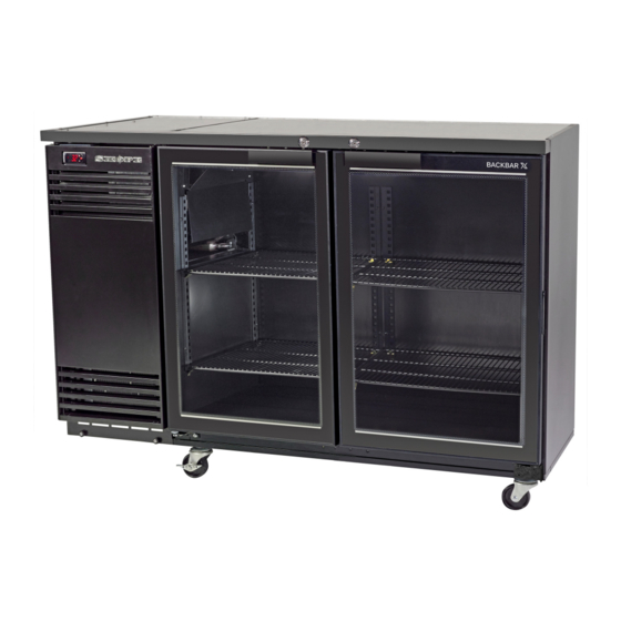
- Page 1 BackBar X SKOPE Horizontal Chiller BB380X-2SW...
- Page 2 E-mail: skope@skope.com Website: www.skope.com Trademark Infringement The SKOPE trademark on this product is infringed if the owner, for the time being, does any of the following: • Applies the trade mark to the product after their state, condition, get-up or packaging has been altered in any manner •...
-
Page 3: Table Of Contents
Shelves ..........38 SKOPE BackBar X... - Page 4 Diagnostic Table ........56 SKOPE BackBar X...
-
Page 5: Specifications
SKOPE BackBar X Specifications Models This service manual is applicable to the SKOPE BackBar X chillers detailed below. The model name is used to distinguish between different models. Model name Part No. Type Doors BB380X-2SW B2412 Integral chiller BB580X-3SW B2413... -
Page 6: Backbar X Integral
SKOPE BackBar X BackBar X Integral BB380X-2SW BB580X-3SW BB780X-4SW Dimensions External Internal External Internal External Internal Height: 920mm* 758mm 920mm* 758mm 920mm* 758mm Width: 1500mm 1020mm 2060mm 1580mm 2620mm 2140mm Depth: 590mm 530mm 590mm 530mm 590mm 530mm Floor area: 0.89m 1.22m... -
Page 7: Backbar X Remote
SKOPE BackBar X BackBar X Remote BB380Xr-2SW BB580Xr-3SW BB780Xr-4SW Dimensions External Internal External Internal External Internal Height: 920mm* 758mm 920mm* 758mm 920mm* 758mm Width: 1355mm 1020mm 1915mm 1580mm 2475mm 2140mm Depth: 590mm 530mm 590mm 530mm 590mm 530mm Floor area: 0.8m 1.13m... -
Page 8: Backbar X Integral Tropical
SKOPE BackBar X BackBar X Integral Tropical BB380XT-2SW BB580XT-3SW BB780XT-4SW Dimensions External Internal External Internal External Internal Height: 920mm* 758mm 920mm* 758mm 920mm* 758mm Width: 1500mm 1020mm 2060mm 1580mm 2620mm 2140mm Depth: 590mm 530mm 590mm 530mm 590mm 530mm Floor area: 0.89m... -
Page 9: Backbar X Remote Tropical
SKOPE BackBar X BackBar X Remote Tropical BB380Xr-2SW BB580Xr-3SW BB780Xr-4SW Dimensions External Internal External Internal External Internal Height: 920mm* 758mm 920mm* 758mm 920mm* 758mm Width: 1355mm 1020mm 1915mm 1580mm 2475mm 2140mm Depth: 590mm 530mm 590mm 530mm 590mm 530mm Floor area: 0.8m... -
Page 10: Electronic Controller
The electronic controller controls and displays the chiller temperature, and signals temperature alarms. To ensure efficient operation, the electronic controller automatically forces a defrost cycle when required. The electronic controller is pre-programmed. SKOPE does not recommend that settings be changed unless it is absolutely necessary. Electronic Controller Service Manual... -
Page 11: Faceplate
SKOPE BackBar X Faceplate Because the electronic controller plays such an important role, it’s helpful to know the parts of the faceplate you may use. Item Description Digital display of cabinet temperature or messages. The temperature is what the sensor inside the chiller detects, and not necessarily the product temperature. -
Page 12: Running The Chiller
SKOPE BackBar X Running the Chiller Operating The electronic controller runs the chiller in constant ‘Normal’ mode. The Modes BackBar X does not use an energy saving/night mode (or similar). Note: Normal mode is suitable for perishable product (all shelves maintain temperature below 5°C). -
Page 13: Messages And Alarms
SKOPE BackBar X Messages and Alarms Controller The following table explains messages and alarms that the electronic Display controller displays. Alarms signal unexpected operational changes in the chiller and can be muted by pressing the set (mute) button on the electronic controller faceplate (see page 11). -
Page 14: Cold Climate Protection
SKOPE BackBar X Cold Climate The chiller will enter cold climate protection (CCP) mode if the ambient Protection temperature becomes too cold. This happens if the control probe (at the evaporator air out) detects the interior temperature below -1°C (parameter St - CCt) for more than 30 minutes (parameter CCd). -
Page 15: Hardware Setup
SKOPE BackBar X Hardware Setup Hardware The controller has three hardware inputs as detailed in the table below. All Inputs use pin 9 as common. Electronic controller hardware inputs Pins (on rear of Hardware description controller) Control probe 9-10 Condenser probe... -
Page 16: Programming The Electronic Controller
The electronic controller parameter configuration program is set by SKOPE at the factory. A label on the controller box indicates the parameter configuration program number (e.g. the BackBar X Series use program 100 (integral) and 103 (remote). The electronic controller parameters can be modified using the keypad. -
Page 17: Parameter History
SKOPE BackBar X Continued over page Category Initial Icon Probe parameters Control parameters Compressor parameters Defrost parameters Alarm parameters Fan parameters 6. Press the Set (mute) button to display the value associated with the parameter code. 7. Use the ES (up) and Light (down) buttons to increase or decrease the value of the parameter. - Page 18 SKOPE BackBar X Parameter list - Program 100 - BackBar X Integral Series (page 1 of 2) Electronic Controller Parameter Sheet Revision: BackBar - X (Integral) Full List Application Controller Type SKOPE S4 EVO SET0 PZSKC0H002K (Rev 1.314) Controller Model & Revision...
- Page 19 1. Only make program modifications with reference to relevant Operating Manual. 2. This programming sheet is exclusively for SKOPE refrigeration systems with its dedicated Carel controller. 3. Any alteration from this program may adversely affect the SKOPE Refrigeration System operation.
- Page 20 SKOPE BackBar X Parameter list - Program 103 - BackBar X Remote Series (page 1 of 2) Electronic Controller Parameter Sheet Revision: BackBar - X (Remote) Full List Application SKOPE S4 EVO Controller Type SET0 PZSKC0H002K (Rev 1.314) Controller Model & Revision...
- Page 21 1. Only make program modifications with reference to relevant Operating Manual. 2. This programming sheet is exclusively for SKOPE refrigeration systems with its dedicated Carel controller. 3. Any alteration from this program may adversely affect the SKOPE Refrigeration System operation.
-
Page 22: Wiring
SKOPE BackBar X Wiring Model: BackBar X Integral Series Isolation Switch GNYE EMC Filter S1-L P1-L P1-N S1-N T1-4 & 5 T1-1, 2 & 3 Compressor Start T1-6 S5-2 P5-2 Carel Overload Relay Smart Controller S5-1 P5-1 S2-4 P2-4 P2-1 S2-1 Compressor Comp. -
Page 23: Model: Backbar X Remote Series
SKOPE BackBar X Model: BackBar X Remote Series Isolation Switch EMC Filter S1-L P1-L P1-N S1-N T1-4 & 5 T1-1, 2 & 3 T1-6 S5-2 P5-2 Carel Smart Controller Optional S5-1 P5-1 S2-4 P2-4 P2-1 S2-1 Solenoid Valve Comp. S2-2 P2-2... -
Page 24: Spare Parts
SKOPE BackBar X Spare Parts Cabinet Assembly ‐ BB‐X Integral Series BB780X-4SW left hand cabinet/unit pictured Spare Parts Service Manual... - Page 25 SKOPE BackBar X Parts — Cabinet Assembly ‐ BB‐X Integral Series No. Description SKOPE Part No. BB380X-2SW BB580X-3SW BB780X-4SW 1 Shelf clip V0973 V0973 V0973 2 Shelf support strip B9702/151AB B9702/151AB B9702/151AB 3 Wire shelf - middle n.a. B2003/160 B2003/160...
-
Page 26: Cabinet Assembly - Bb-X Remote Series
SKOPE BackBar X Cabinet Assembly ‐ BB‐X Remote Series BB780Xr-4SW left hand cabinet/unit pictured Spare Parts Service Manual... - Page 27 SKOPE BackBar X Parts — Cabinet Assembly ‐ BB‐X Remote Series No. Description SKOPE Part No. BB380Xr-2SW BB580Xr-3SW BB780Xr-4SW 1 Shelf clip V0973 V0973 V0973 2 Shelf support strip B9702/151AB B9702/151AB B9702/151AB 3 Wire shelf - middle n.a. B2003/160 B2003/160...
-
Page 28: Door Assembly
SKOPE BackBar X Door Assembly Parts — Door Assembly No. Description SKOPE Part No. Door assembly - RH standard GLD11431R Door assembly - RH tropical GLD11432R Door assembly - LH standard GLD11431L Door assembly - LH tropical GLD11432L Gasket GKT11546... -
Page 29: Mains Isolation Box Assembly
SKOPE BackBar X Mains Isolation Box Assembly Mains Isolation Box Assembly - BB-X Integral Mains Isolation Box Assembly - BB-Xr Remote Parts — Mains Isolation Box Assembly ‐ BB‐X Integral No. Description SKOPE Part No. Mains isolation box and flex assembly - RH... -
Page 30: Electronic Controller Assembly
SKOPE BackBar X Electronic Controller Assembly Electronic Controller Assembly - BB-X Integral Electronic Controller Assembly - BB-Xr Remote Parts — Electronic Controller Assembly ‐ BB‐X Integral No. Description SKOPE Part No. Electronic controller assembly UE40ABF/K01-100 CAREL S4 Evo electronic controller... -
Page 31: Unit Electrics Box Assembly
SKOPE BackBar X Unit Electrics Box Assembly Parts — Unit Electrics Box Assembly No. Description SKOPE Part No. Unit electrics box assembly (RH unit) UE40ABF/R86R Unit electrics box assembly (LH unit) UE40ABF/R86L Fuse (5A) ELZ9640 Fuse holder ELZ9655 Unit electrics box lid... -
Page 32: Refrigeration Unit Assembly - Bb-X Integral
SKOPE BackBar X Refrigeration Unit Assembly ‐ BB‐X Integral UE30ABF LH unit pictured Spare Parts Service Manual... - Page 33 SKOPE BackBar X Parts — Refrigeration Unit Assembly ‐ BB‐X Integral No. Description SKOPE Part No. Refrigeration unit assembly - RH UE40ABF-100ICR UE30ABF-100ICR (used in BB380X/580X and (used in BB780X and BB380XT) BB580XT/780XT) Refrigeration unit assembly - LH UE40ABF-100IC (used in...
-
Page 34: Refrigeration Unit Assembly - Bb-Xr Remote
SKOPE BackBar X Refrigeration Unit Assembly ‐ BB‐Xr Remote UE30ABR LH unit pictured Parts — Refrigeration Unit Assembly ‐ BB‐Xr Remote No. Description SKOPE Part No. Refrigeration unit assembly - RH UE40ABR-103IDR UE30ABR-103IDR (used in BB380Xr/580Xr and (used in BB780Xr and... -
Page 35: Installation
Adequate allowance should be made for door opening. Always ensure that the top of the cabinet is shielded from impact and moisture, with either a SKOPE provided bench top, or with a custom or existing bench top. When installing the cabinet Avoid direct sunlight and warm draughts etc. -
Page 36: Power Cord
SKOPE BackBar X Power Cord The chiller is supplied with a flexible power cord and plug, which is located at the rear of the cabinet. Before final positioning of the cabinet, pull the power cord out from the cabinet and connect to the power supply. -
Page 37: Positioning The Cabinet
SKOPE BackBar X Positioning the Cabinet Legs and The chiller is packed with a set of adjustable height legs and a set of Castors adjustable height castors. The legs can adjust the cabinet height up to 30mm, and the castors can adjust the cabinet height up to 15mm. -
Page 38: Shelves
SKOPE BackBar X Shelves The chiller is fitted with wire shelves, which may be positioned at different heights to suit various products. Fitting the Remove all packaging material from the shelves. Clip the shelf support Shelves brackets into the shelf support strips, at the desired heights, and fit the shelves. -
Page 39: Remote Cabinet Installation
SKOPE BackBar X Remote Cabinet Installation Only applicable for cabinets with remote refrigeration systems. SKOPE horizontal remote cabinets are supplied with a seperate instruction sheet: Guidelines for SKOPE remote Refrigeration (PRN2362). Refer to this sheet for SKOPE remote refrigeration installation guidelines and specifications. -
Page 40: Replacement Procedures
SKOPE BackBar X Replacement Procedures Isolating Electrics To isolate the chiller from the power supply, either unplug the cabinet from the wall, or use the isolation switch to turn off electrics to the cabinet and refrigeration unit. The isolation switch is located behind the unit cover, inside the refrigeration unit compartment. -
Page 41: Lighting
SKOPE BackBar X Lighting This chiller is designed for use with LED tube lights and is not compatible with fluorescent tubes. IMPORTANT DO NOT use fluorescent tubes. The chiller is fitted with one T8 LED tube light, which can be replaced without moving shelves or product. -
Page 42: Doors
SKOPE BackBar X Doors Alignment Door alignment can be achieved by releasing the bottom hinge fixing bracket. The bracket is provided with slots allowing alignment adjustment. Gasket The door gasket clips into the door gasket retainer extrusion on the inside of the door and may be removed for repair or replacement by peeling from the frame, starting at a corner. -
Page 43: Tension Adjustment
SKOPE BackBar X 3. Once adequate tension has been achieved, re-insert the split pin through the hole in the hinge bracket to lock in position. 4. To check door tension, hold the door open approximately 100mm and let go of the door. The door should gently close, with the door gasket forming an air tight seal with the cabinet. -
Page 44: Integral Refrigeration Unit
SKOPE BackBar X Integral Refrigeration Unit Refrigeration The SKOPE BackBar X integral refrigeration unit is an end mounted, Unit Assembly removable refrigeration unit. Depending on the cabinet specification, the refrigeration unit is LH end mounted or RH end mounted. The unit is end specific and cannot be reversed (LH unit pictured). -
Page 45: Unit Electrics Box
SKOPE BackBar X Unit Electrics The unit electrics box houses fuses, refrigeration unit electrics, and refrigeration unit and cabinet connectors. The unit electrics box is fixed onto the front of the refrigeration unit, and can be accessed by removing the unit front cover. -
Page 46: Refrigeration Unit Removal
SKOPE BackBar X Refrigeration Follow the steps below to remove the refrigeration unit from the cabinet. Unit Removal To remove the refrigeration unit from cabinet 1. Remove the unit cover, switch off (O) the isolation switch and unplug the power plug from the isolation box. -
Page 47: Evaporator Fan Assembly
SKOPE BackBar X Evaporator The evaporator fan assembly is made up of a fan motor, fan blade and a Fan Assembly mounting bracket which can be replaced if necessary. If the fan stops for any reason, check all connections to ensure no plugs have come loose. -
Page 48: Condenser Fan Assembly
SKOPE BackBar X To replace the evaporator fan blade 1. Remove the unit front cover and isolate the chiller fom the power supply (see page 40). 2. Remove the evaporator fan assembly (see page 47). 3. Detach the evaporator fan blade from the fan motor. -
Page 49: Recommended Service Procedures
Cyclone® serial/rating label. All service lines must be purged. Finally, pinch-off the gauge process lines (or remove line piercing valves) and braze the system closed. SKOPE recommend against leaving service valves in the system as these are prone to leak (and are open to abuse). - Page 50 The drier must be replaced every time the system is opened. Clean work practices are essential. SKOPE recommend brazing the system closed after service, as valves are prone to leak due to the nature of R134a. Replacement Procedures...
-
Page 51: Electronic Controller
SKOPE BackBar X Electronic Controller Electronic The electronic controller is located within the electronic controller box Controller assembly. Location To access the controller 1. Remove the unit cover and isolate the chiller from the power supply (see page 40). 2. Open the electronic controller box assembly by undoing the two fixing screws at the rear of the assembly. -
Page 52: Probe Resistance
SKOPE BackBar X Probe Resistance Table of temperature-resistance values for NTC sensor 10K@25°C ß 3435 Temp. Resistance value Temp. Resistance value Temp. Resistance value Max. Typical Min. Max. Typical Min. Max. Typical Min. °C KΩ KΩ KΩ °C KΩ KΩ... -
Page 53: Control Probe
SKOPE BackBar X Control Probe The control probe is located in the evaporator box, cable tied to a bracket under the evaporator coil (see image below). To replace the control probe 1. Remove the unit cover and isolate the chiller from the power supply (see page 40). -
Page 54: Condenser Probe
SKOPE BackBar X 6. Following the same path as the original probe, run the new probe into the evaporator box (use cable ties to hold the probe cable in place). Feed the probe into the 8th fin on the evaporator coil, and push 200mm into the coil. -
Page 55: Maintenance
SKOPE BackBar X Maintenance Cleaning Condenser To ensure trouble-free performance, we strongly urge monthly cleaning with Coil a soft brush to remove dust and fluff. A more thorough cleaning is required by qualified service personnel every six months. The condenser coil must be kept clean for efficient and reliable operation. -
Page 56: Troubleshooting
SKOPE BackBar X Troubleshooting Diagnostic Table For questions about the electronic controller, see page 10. For problems with the cabinet and refrigeration unit, use the following table. Cabinet Problem Possible Cause Suggestions Cabinet not operating • Isolation switch off • Turn the isolation switch on (I) (see... - Page 57 SKOPE BackBar X Problem Possible Cause Suggestions Compressor will not start: • Improperly wired. • Check wiring against diagram (see hums but trips on overload page 22). protector. • Low voltage to unit. • Determine reason and correct. • Start capacitor defective on •...
- Page 58 SKOPE BackBar X Problem Possible Cause Suggestions Unit operates long or • Short of refrigerant. • Fix leak, and add charge. continuously. Unsatisfactory • Overcharge of refrigerant. • Remove refrigerant to correct charge. cabinet temperature. • Chiller has excessive load.
- Page 59 SKOPE Industries Limited A.B.N. 73 374 418 306 AU: 1800 121 535 NZ: 0800 947 5673 skope@skope.com www.skope.com...
Need help?
Do you have a question about the BackBar X Series and is the answer not in the manual?
Questions and answers