
Related Manuals for ITT Goulds Pumps ICM


Summary of Contents for ITT Goulds Pumps ICM
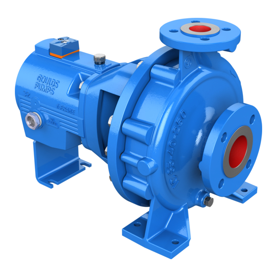
- Page 1 Installation, Operation, and Maintenance Manual Model ICM/ICMP Magnetic Drive Chemical Process Pump with Grease Bearing Lubrication...
-
Page 3: Table Of Contents
Table of Contents Table of Contents 1 Safety.................................. 3 1.1 Important Safety Notice..........................3 1.2 Safety warnings............................3 1.3 Safety ................................ 4 1.4 General precautions ..........................5 1.5 ATEX Considerations and Intended Use....................7 1.6 Parts ................................9 2 Technical data..............................10 2.1 Technical data ............................ - Page 4 Table of Contents 7 Maintenance..............................27 7.1 Screw connections of the housing......................27 7.2 Bearing pedestal ............................. 27 7.3 Cleaning ..............................27 7.4 Stand-by pumps ............................28 7.5 Notes on dismantling..........................28 7.5.1 Protective clothes.......................... 28 7.5.2 Magnetic fields ..........................28 7.5.3 Changing the radial ball bearings....................
-
Page 5: Safety
ITT Goulds pumps will provide safe, trouble-free service when properly installed, maintained, and operat- Safe installation, operation, and maintenance of ITT Goulds Pumps equipment are an essential end user responsibility. This Pump Safety Manual identifies specific safety risks that must be considered at all times during product life. -
Page 6: Safety
Trapped liquid can rapidly expand and result in a violent explosion and injury. ITT Goulds Pumps will not accept responsibility for physical injury, damage, or delays caused by a failure to observe the instructions for installation, operation, and maintenance contained in this Pump Safety Manual or the current IOM available at www.gouldspumps.com/literature. -
Page 7: General Precautions
Personal injuries will result if procedures outlined in this manual are not followed. ITT Goulds Pumps will not accept responsibility for physical injury, damage or delays caused by a failure to observe the instructions in this manual and the IOM provided with your equip- ment. - Page 8 1.4 General precautions WARNING Alignment: Shaft alignment procedures must be followed to prevent catastrophic failure of drive components or unintended contact of rotating parts. Follow coupling manufacturer's coupling installation and operation procedures. WARNING Before beginning any alignment procedure, make sure driver power is locked out. Fail- ure to lock out driver power will result in serious physical injury.
-
Page 9: Atex Considerations And Intended Use
1.5 ATEX Considerations and Intended Use CAUTION Never operate the pump without liquid supplied to mechanical seal. Running a mechani- cal seal dry, even for a few seconds, can cause seal damage and must be avoided. Physical injury can occur if mechanical seal fails. WARNING Never attempt to replace packing until the driver is properly locked out and the coupling spacer is removed. - Page 10 Maintenance manual (IOM) can cause serious personal injury or damage to the equipment. This in- cludes any modification to the equipment or use of parts not provided by ITT Goulds Pumps. If there is any question regarding the intended use of the equipment, please contact an ITT Goulds representative before proceeding.
-
Page 11: Parts
1.6 Parts The use of genuine Goulds parts will provide the safest and most reliable operation of your pump. ITT Goulds Pumps ISO certifica- tion and quality control procedures ensure the parts are manufac- tured to the highest quality and safety levels. -
Page 12: Technical Data
2 Technical data 2 Technical data 2.1 Technical data Manufacturer ITT Goulds Pumps Millwey Rise Industrial Estate Axminster, Devon, EX13 5HU Tel : +44 (0)1297-639100 Fax : +44 (0)1297-630476 Designation Model ICM Magnetic Chemical Process Pump, bearing lubrication: grease. Model ICMP Magnetic Chemical Process Pump for high pressure / high temperature applications, with center-line mounted casing, bearing lubrication: grease. -
Page 13: Intended Use
2.2 Intended use With temperatures up to 280° C oil bath lubrication has to be used Temperature classes Refer to Temperature limits NOTICE: Consult the manufacturer for higher pressures and lower or higher temperatures. Sizes Group 1 Group 2.1 Group 2.2 100-65-160 40-25-160 40-25-250... -
Page 14: Tightening Torques
2.3 Tightening torques The observance of the specified physical limits is important for perfect functioning and safe operation, especially with regard to explosion protection to prevent potential sources of ignition (see Explosion pro- tection. • It must be ensured that the pump is always filled with liquid during operation. •... -
Page 15: Type Plate, Dry-Running, Ce And Housing Markings
2.4 Type plate, dry-running, CE and housing markings Table 4: Housing screws 901/3 - Group 2.1 Pump size No. x size 100-65-160 12 x M12 125-80-160 12 x M12 100-65-200 12 x M12 125-80-200 12 x M12 125-100-200 12 x M12 Table 5: Housing screws 901/3 - Group 2.2 Pump size No. - Page 16 2.4 Type plate, dry-running, CE and housing markings Figure 2: Example of type plate CE-marking Figure 3: When CE applies Figure 4: When CE & ATEX applies Housing identification The following are visible on the housing according to DIN EN 19: •...
-
Page 17: Transport And Storage
3 Transport and storage 3 Transport and storage 3.1 Transport and storage WARNING: The pump or the unit must be transported properly. It must be ensured that during transport the pump/unit remains in the horizontal position and does not slip out of the transport suspension points. -
Page 18: Return Consignments
3.1 Transport and storage CAUTION: When unpacking magnetic drives as single parts, the relevant notes in 7.5 Notes on disman- tling on page 28 must be observed. Handle goods carefully to prevent damage. Flange covers serve as protection during transport and must not be removed. If the unit is not installed immediately after delivery, it must be put into proper storage. -
Page 19: Product Description
4 Product description 4 Product description 4.1 General description The housing dimensions of the pump model ICM comply with ISO 2858 / DIN EN 22858. The technical requirements and nominal ratings of the pump models ICMB comply with ISO 2858 / DIN EN 22858 / ISO 15783 / DIN ISO 5199. - Page 20 4.1 General description Design details are provided in the sectional drawing, 9.1 Sectional drawings and parts list on page Additional information is also contained in the Brochure and Pricebook. Model ICM/ICMP Magnetic Drive Chemical Process Pump with Grease Bearing Lubrication Installation, Operation, and Maintenance Manual...
-
Page 21: Installation
5 Installation 5 Installation 5.1 Safety regulations WARNING: • Equipment which is operated in potentially explosive areas must satisfy the explosion protection regulations. • People with a pacemaker are at risk from the strong magnetic field of the magnetic drive. It may be life-threatening for them to stay at a distance of less than 500 mm to the pump. -
Page 22: Piping
5.4 Piping 5.4 Piping Before the pump is installed, both, the suction and supply lines as well as the discharge line are to be cleaned. Dirt or damage to the sealing surfaces is best avoided if the flange covers remain on the flanges until just before installation. -
Page 23: Nozzle Loads
5.5 Monitoring facilities 5.4.2 Nozzle loads The pump can be subjected to nozzle loads in accordance with ISO 5199. See also Pricebook. Changes in the length of the piping caused by temperature are to be allowed for by appropriate meas- ures, e.g. -
Page 24: Drive
If the motor power exceeds this rating, it is necessary to check the stoppage of the magnetic drive. The same also applies if the required drive rating exceeds 80 % of the magnetic drive rating. Consult ITT Goulds if necessary. Different operating data can be achieved without changing the pump through the use of different speeds, e.g. -
Page 25: Coupling Guard
5.8 Coupling guard 5.8 Coupling guard The pump may only be operated with a coupling guard in accordance with the accident prevention regu- lations. WARNING: The coupling guard used in an ATEX classified environment must be constructed from a spark resistant material. -
Page 26: Commissioning/Shutdown
6 Commissioning/Shutdown 6 Commissioning/Shutdown 6.1 Initial commissioning Normally, the pumps have already been test-run with water. Unless special agreements have been made, there could still be residual amounts of water in the pump. This must be noted in view of a possi- ble reaction with the medium. -
Page 27: Operating Limits
6.2 Operating limits CAUTION: When the motor is running but the pump is not conveying, this means that the magnetic drive has stopped. Switch the motor off immediately to prevent overheating of the magnets. Then proceeded as follows: Close discharge valve down to the position minimum flow rate. Start motor again. -
Page 28: Inadmissible Modes Of Operations And Their Consequences (Examples)
6.5 Inadmissible modes of operations and their consequences (examples) 6.5 Inadmissible modes of operations and their consequences (examples) CAUTION: Inadmissible modes of operation, even for a short time, can result in serious damage to the unit. In connection with explosion protection, potential sources of ignition (overheating, electrostatic and in- duced charges, mechanical and electric sparks) may result from these inadmissible modes of operation;... -
Page 29: Maintenance
7 Maintenance 7 Maintenance 7.1 Screw connections of the housing After initial loading by the operating pressure and operating temperature the tightening torques of all con- nection screws must be checked at the following points: • housing flange • suction flange •... -
Page 30: Stand-By Pumps
7.4 Stand-by pumps 7.4 Stand-by pumps If a pump is on stand-by, it is to be started up from time to time. Regularly turn the shaft by hand in the direction of rotation. This operation is to be performed more often for pumps which are exposed to very strong vibrations from the plant. -
Page 31: Changing The Radial Ball Bearings
7.6 Dismantling • Data carriers such as credit cards, cheque cards, ID cards with magnetic strips or mag- netic tapes: 150 mm distance. 7.5.3 Changing the radial ball bearings When changing the radial ball bearings, you merely need to remove the bearing pedestal from the plant. For removal and dismantling of the bearing pedestal, see 7.6.1 Remove bearing pedestal on page 29 7.6.2 Dismantling bearing pedestal on page... -
Page 32: Removing Lantern, Can And Plain Bearing Pedestal
7.7 Notes on assembly 7.6.3 Removing lantern, can and plain bearing pedestal Undo housing screwing (901/3), (554/3). Do not undo the two screws (901/5) (if installed). They hold the lantern (344), can (159) and plain bearing pedestal (339) together. Pull the entire slide-in unit out of the housing (100). If the housing does not move (e.g. -
Page 33: Assembly
7.8 Assembly 7.8 Assembly A complete assembly operation is described in the following. Sub-sections can be deduced from this. 7.8.1 Assemble bearing pedestal Press both radial ball bearings 321 onto the drive shaft 213. Insert key 940/1 into the drive shaft. Install the pre-assembled drive shaft into the bearing pedestal from the motor side. -
Page 34: Final Assembly
7.9 Tests Mount can (159) and lantern (344). Screw the two connection screws (901/5) or the 3 setscrews (904/2) (depending on size) of the lan- tern (344) into the plain bearing pedestal (339) and tighten. 7.8.5 Final assembly Secure the housing (100) with the suction nozzle facing downwards on a workbench or worktop. Insert the housing gasket (401) into the housing centering. -
Page 35: Faults
8 Faults 8 Faults 8.1 Faults Faults may result from inadmissible modes of operation. Such inadmissible modes of operation – even brief ones – may cause serious damage to the unit. In connection with explosion protection, potential sources of ignition (overheating, electrostatic and in- duced charges, mechanical and electric sparks) can result from these inadmissible modes of operation;... - Page 36 8.1 Faults • Is the flow rate, density or viscosity too high? • Is the coupling correctly aligned? • Can the drive shaft be turned properly? Pump does not run smoothly or creates noises: • Is the coupling well aligned? •...
-
Page 37: Sectional Drawing
9 Sectional drawing 9 Sectional drawing 9.1 Sectional drawings and parts list ICM and ICMP with grease for life parts list Item Number Description Housing Case drain plug Support bracket Drive shaft Impeller Impeller nut Plain bearing cartridge 321/x Radial ball bearing Bearing pedestal Plain bearing pedestal Lantern... - Page 38 9.1 Sectional drawings and parts list ICM with grease for life lubrication cutout view - only with group1-160 and 2-160/200 Model ICM/ICMP Magnetic Drive Chemical Process Pump with Grease Bearing Lubrication Installation, Operation, and Maintenance Manual...
- Page 39 9.1 Sectional drawings and parts list ICMP with grease for life lubrication "X" - only with group1-160 and 2-160/200 Model ICM/ICMP Magnetic Drive Chemical Process Pump with Grease Bearing Lubrication Installation, Operation, and Maintenance Manual...
- Page 40 Visit our website for the latest version of this document and more information: http://www.gouldspumps.com ITT Goulds Pumps Inc. 240 Fall Street Senenca Falls 13148 Form IOM.ICM/ICMP-Grease.en-US.2020-05 ©2020 ITT Goulds Pumps, Inc. The original instruction is in English. All non-English instructions are translations of the original instruction.
Need help?
Do you have a question about the Goulds Pumps ICM and is the answer not in the manual?
Questions and answers