Sign In
Upload
Download
Add to my manuals
Delete from my manuals
Share
URL of this page:
HTML Link:
Bookmark this page
Add
Manual will be automatically added to "My Manuals"
Print this page
×
Bookmark added
×
Added to my manuals
Manuals
Brands
Profile Design Manuals
Bicycle Accessories
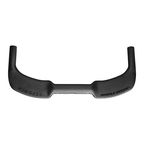
WING/20c
Instructions manual
Profile Design WING/20c Instructions Manual
Basebar
Hide thumbs
1
2
3
4
5
6
7
8
9
10
11
12
13
14
15
16
17
18
19
page
of
19
Go
/
19
Bookmarks
Advertisement
Quick Links
Download this manual
Basebar
BASEBAR
REVISION 01-12-22-2020
1
Table of
Contents
Previous
Page
Next
Page
1
2
3
4
5
Advertisement
Need help?
Do you have a question about the WING/20c and is the answer not in the manual?
Ask a question
Questions and answers
Related Manuals for Profile Design WING/20c
Bicycle Accessories Profile Design WING/c Instructions Manual
Basebar (19 pages)
Bicycle Accessories Profile Design WING/10A Instructions Manual
Basebar (19 pages)
Bicycle Accessories Profile Design WING/A Instructions Manual
Basebar (19 pages)
Bicycle Accessories Profile Design WING20C+ Manual
Aerobar (19 pages)
Bicycle Accessories Profile Design DRV SIZER BAR Manual
(9 pages)
Bicycle Accessories Profile Design AEROPORT Owner's Manual
(11 pages)
Bicycle Accessories Profile Design AERIA1 EVO Manual
Aerobar (20 pages)
Bicycle Accessories Profile Design AERIA ULTIMATE RACE Manual
Bracket (17 pages)
Bicycle Accessories Profile Design DRV/GMR Series Instructions Manual
Handlebar (9 pages)
Bicycle Accessories Profile Design 43ASC Manual
Extensions (12 pages)
Bicycle Accessories Profile Design HSC250 Quick Start Manual
Top tube flask (9 pages)
Bicycle Accessories Profile Design Split Second Installation Instructions
Aerobar w/ multi-fit system (2 pages)
Bicycle Accessories Profile Design HSA 800 EVO HYDRATION Manual
(13 pages)
Bicycle Accessories Profile Design 35SLC Manual
Aerobar extensions (18 pages)
Bicycle Accessories Profile Design T2+ DL Installation Instructions
Aerobar w/ multi-fit system (2 pages)
Bicycle Accessories Profile Design HSF AERODRINK 880 BOTTLE KIT Quick Start Manual
(10 pages)
This manual is also suitable for:
Wing/c
Wing/10a
Wing/a
Ozero tt
Print
Rename the bookmark
Delete bookmark?
Delete from my manuals?
Login
Sign In
OR
Sign in with Facebook
Sign in with Google
Upload manual
Upload from disk
Upload from URL


Need help?
Do you have a question about the WING/20c and is the answer not in the manual?
Questions and answers