Table of Contents
Advertisement
Quick Links
Advertisement
Table of Contents

Subscribe to Our Youtube Channel
Related Manuals for Seco SBC-C90


Summary of Contents for Seco SBC-C90
- Page 1 SBC-C90 V1000 family of SOCs...
- Page 2 SECO S.p.A. reserves the right to change precise specifications without prior notice to supply the best product possible. For further information on this module or other SECO products, but also to get the required assistance for any and possible issues, please contact us using the dedicated web form available at http://www.seco.com (registration required).
-
Page 3: Table Of Contents
M.2 2280 Socket 3 Key M NVMe Slot ................................... 32 3.3.10 M.2 3042 Socket 2 Key B WWAN Slot ..................................34 SBC-C90 SBC-C90 User Manual - Rev. First Edition: 1.0 - Last Edition: 1.0 - Author: A.R. - Reviewed by C.M. Copyright © 2021 SECO S.p.A. - Page 4 Network Stack configuration submenu ................................... 54 4.3.21 AMD CBS submenu ........................................54 4.3.22 AMD Platform submenu ....................................... 57 SBC-C90 SBC-C90 User Manual - Rev. First Edition: 1.0 - Last Edition: 1.0 - Author: A.R. - Reviewed by C.M. Copyright © 2021 SECO S.p.A.
- Page 5 Boot menu ............................................60 Save & Exit menu ..........................................61 APPENDICES .....................................62 Thermal Design ........................................... 63 SBC-C90 SBC-C90 User Manual - Rev. First Edition: 1.0 - Last Edition: 1.0 - Author: A.R. - Reviewed by C.M. Copyright © 2021 SECO S.p.A.
-
Page 6: Introduction
• Safety • Electrostatic discharges • RoHS compliance • Terminology and definitions • Reference specifications SBC-C90 SBC-C90 User Manual - Rev. First Edition: 1.0 - Last Edition: 1.0 - Author: A.R. - Reviewed by C.M. Copyright © 2021 SECO S.p.A. -
Page 7: Warranty
All changes or modifications to the equipment not explicitly approved by SECO S.p.A. could impair the equipment s functionalities and could void the warranty SBC-C90 SBC-C90 User Manual - Rev. First Edition: 1.0 - Last Edition: 1.0 - Author: A.R. - Reviewed by C.M. Copyright © 2021 SECO S.p.A. -
Page 8: Information And Assistance
A RMA Number will be sent within 1 working day (only for on-line RMA requests). SBC-C90 SBC-C90 User Manual - Rev. First Edition: 1.0 - Last Edition: 1.0 - Author: A.R. - Reviewed by C.M. Copyright © 2021 SECO S.p.A. -
Page 9: Safety
Check carefully that all cables are correctly connected and that they are not damaged. 1.5 Electrostatic discharges The SBC-C90 board, like any other electronic product, is an electrostatic sensitive device: high voltages caused by static electricity could damage some or all the devices and/or components on-board. -
Page 10: Terminology And Definitions
Open Graphics Library, an Open Source API dedicated to 2D and 3D graphics Operating System PCI-e Peripheral Component Interface Express Power Supply Unit SBC-C90 SBC-C90 User Manual - Rev. First Edition: 1.0 - Last Edition: 1.0 - Author: A.R. - Reviewed by C.M. Copyright © 2021 SECO S.p.A. - Page 11 Unified Memory Architecture, synonym of Integrated Graphics, uses a portion of a computer’s system RAM dedicated to graphics rather than using dedicated graphics memory only. Universal Serial Bus V_REF Voltage reference Pin SBC-C90 SBC-C90 User Manual - Rev. First Edition: 1.0 - Last Edition: 1.0 - Author: A.R. - Reviewed by C.M. Copyright © 2021 SECO S.p.A.
-
Page 12: Reference Specifications
TMDS https://www.cablestogo.com/learning/library/digital-signage/intro-to-tmds UEFI http://www.uefi.org USB 2.0 and USB OTG https://www.usb.org/sites/default/files/usb_20_20190524.zip USB 3.0 https://usb.org.10-1-108-210.causewaynow.com/sites/default/files/usb_32_20191024.zip V1000 family SBC-C90 SBC-C90 User Manual - Rev. First Edition: 1.0 - Last Edition: 1.0 - Author: A.R. - Reviewed by C.M. Copyright © 2021 SECO S.p.A. -
Page 13: Overview
• Introduction • Technical specifications • Electrical specifications • Mechanical specifications • Block diagram SBC-C90 SBC-C90 User Manual - Rev. First Edition: 1.0 - Last Edition: 1.0 - Author: A.R. - Reviewed by C.M. Copyright © 2021 SECO S.p.A. -
Page 14: Introduction
M.2 Socket 1 Key E Slot for WiFi+BT M.2 modules. Further features usable on SBC-C90 board are four USB ports (two USB 3.0 and two USB 2.0 only), HD Audio, 2x RS-232/RS-422/RS-485 UARTS, 8 x GPI/Os, 2x I2C, one Antitamper connector, and optional TPM 1.2 or 2.0 on board. -
Page 15: Technical Specifications
** Measured at any point of SECO standard heatspreader for this product, during any and all times (including start-up). Actual temperature will widely depend on application, enclosure and/or environment. Upon customer to consider application-specific cooling solutions for the final system to keep the heatspreader temperature in the range indicated. -
Page 16: Electrical Specifications
2.3 Electrical specifications SBC-C90 board can be supplied using any voltage in the range +12 . All the others voltages necessary for the working of the board and of the connected peripherals are derived from the main V power rail ®... -
Page 17: Power Consumption
Battery Backup power consumption: Soft-Off State power consumption: 105mA Soft-Off State power consumption: 119mA SBC-C90 SBC-C90 User Manual - Rev. First Edition: 1.0 - Last Edition: 1.0 - Author: A.R. - Reviewed by C.M. Copyright © 2021 SECO S.p.A. -
Page 18: Rtc Battery
Batteries supplied with SBC-C90 are compliant to requirements of European Directive 2006/66/EC regarding batteries and accumulators. When putting out of order SBC-C90, remove the batteries from the board in order to collect and dispose them according to the requirement of the same European Directive above mentioned. -
Page 19: Mechanical Specifications
The printed circuit of the board is made of ten layers, some of them are ground planes, for disturbance rejection. SBC-C90 SBC-C90 User Manual - Rev. First Edition: 1.0 - Last Edition: 1.0 - Author: A.R. - Reviewed by C.M. Copyright © 2021 SECO S.p.A. -
Page 20: Block Diagram
Dual USB 2.0 pin USB 2.0 #0 #3 Optional TPM FAN Connectors header Antitamper Intruder_Alert BIOS Flash connector SBC-C90 SBC-C90 User Manual - Rev. First Edition: 1.0 - Last Edition: 1.0 - Author: A.R. - Reviewed by C.M. Copyright © 2021 SECO S.p.A. -
Page 21: Connectors
• Introduction • Connectors overview • Connectors description SBC-C90 SBC-C90 User Manual - Rev. First Edition: 1.0 - Last Edition: 1.0 - Author: A.R. - Reviewed by C.M. Copyright © 2021 SECO S.p.A. -
Page 22: Introduction
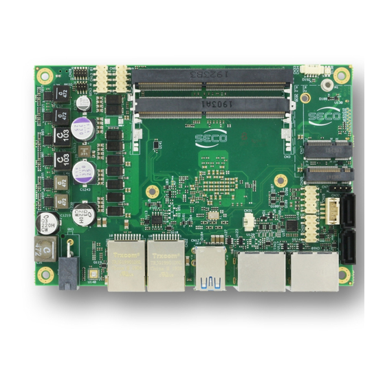
3.1 Introduction On SBC-C90 board, there are several connectors located on the lower plane. Standard connectors are placed on the same side of PCB, so that it is possible to place them on a panel of an eventual enclosure. Please be aware that, depending on the configuration purchased, the appearance of the board could be slightly different from the following pictures. -
Page 23: Connectors Overview
M.2 2230 Socket 1 Key E (Connectivity Slot) Power Button CN18 M.2 2280 Socket 3 Key M (NVMe Slot) SBC-C90 SBC-C90 User Manual - Rev. First Edition: 1.0 - Last Edition: 1.0 - Author: A.R. - Reviewed by C.M. Copyright © 2021 SECO S.p.A. -
Page 24: Connectors Description
DDR4 SO-DIMM Sockets CPUs used on the SBC-C90 board provide support to DDR4 SO-DIMM Memory Modules, up to 32GB total, which can be integrated by using the dedicated DDR4 SO-DIMM sockets CN2 and CN3. Both ECC and non-ECC memory modules are supported. -
Page 25: Intruder Header
CN11 (i.e. Port #A, or DP Port #2) will be not working. SBC-C90 SBC-C90 User Manual - Rev. First Edition: 1.0 - Last Edition: 1.0 - Author: A.R. - Reviewed by C.M. Copyright © 2021 SECO S.p.A. -
Page 26: Audio Header
Line_Out_R: Analog Port 2 - Headphone Right Channel. Sense2_Return: Analog Port 2 - Jack detection return signal. S/PDIF_Out: S/PDIF AC-coupled output. SBC-C90 SBC-C90 User Manual - Rev. First Edition: 1.0 - Last Edition: 1.0 - Author: A.R. - Reviewed by C.M. Copyright © 2021 SECO S.p.A. -
Page 27: Usb Connectors
USB_SSRX1+/USB_SSRX1-: USB Super Speed Port #1 receive differential pair USB_SSTX1+/USB_SSTX1-: USB Super Speed Port #1 transmit differential pair SBC-C90 SBC-C90 User Manual - Rev. First Edition: 1.0 - Last Edition: 1.0 - Author: A.R. - Reviewed by C.M. Copyright © 2021 SECO S.p.A. - Page 28 For ESD protection, on all data and voltage lines are placed clamping diodes for voltage transient suppression. SBC-C90 SBC-C90 User Manual - Rev. First Edition: 1.0 - Last Edition: 1.0 - Author: A.R. - Reviewed by C.M. Copyright © 2021 SECO S.p.A.
-
Page 29: Sata Connectors
Mating connector: HR A2001H-04P housing with HR A2001 series crimp terminals. +5V_SATA (1.8A max) SBC-C90 SBC-C90 User Manual - Rev. First Edition: 1.0 - Last Edition: 1.0 - Author: A.R. - Reviewed by C.M. Copyright © 2021 SECO S.p.A. -
Page 30: 2230 Socket 1 Key E Connectivity Slot
PCIE_RST#: Reset Signal that is sent from the SoC to all PCI-e devices available on the SBC-C90 SBC-C90 User Manual - Rev. First Edition: 1.0 - Last Edition: 1.0 - Author: A.R. - Reviewed by C.M. Copyright © 2021 SECO S.p.A. - Page 31 WIFI_DISABLE#: M.2 Key E Wireless module functionality disable signal #2, active low signal, +3.3V_ALW electrical level SBC-C90 SBC-C90 User Manual - Rev. First Edition: 1.0 - Last Edition: 1.0 - Author: A.R. - Reviewed by C.M. Copyright © 2021 SECO S.p.A.
-
Page 32: 2280 Socket 3 Key M Nvme Slot
PCIE_GFX_Rx3+/ PCIE_GFX_Rx3-: PCI Express lane #3, Receiving Input Differential pair PCIE_GFX_Tx0+ PCIE_RST# NVME_CLK+ / NVME_CLK-: PCI Express Reference Clock, Differential Pair CLK_REQ4# SBC-C90 SBC-C90 User Manual - Rev. First Edition: 1.0 - Last Edition: 1.0 - Author: A.R. - Reviewed by C.M. Copyright © 2021 SECO S.p.A. - Page 33 PCIE_RST#: Reset Signal that is sent from the SoC to all PCI-e devices available on the board. It is a +3.3V_RUN active-low signal. SBC-C90 SBC-C90 User Manual - Rev. First Edition: 1.0 - Last Edition: 1.0 - Author: A.R. - Reviewed by C.M. Copyright © 2021 SECO S.p.A.
-
Page 34: 3042 Socket 2 Key B Wwan Slot
It must be externally driven by the Connectivity module plugged in the slot when it requires waking up the system. SBC-C90 SBC-C90 User Manual - Rev. First Edition: 1.0 - Last Edition: 1.0 - Author: A.R. - Reviewed by C.M. Copyright © 2021 SECO S.p.A. - Page 35 Signals related to SD cards are the following: SDIO_CD#: Card Detect Input. SDIO_CLK: SD Clock Line (output). SDIO_CMD: Command/Response bidirectional line. SBC-C90 SBC-C90 User Manual - Rev. First Edition: 1.0 - Last Edition: 1.0 - Author: A.R. - Reviewed by C.M. Copyright © 2021 SECO S.p.A.
- Page 36 GBEx_MDI3+/GBEx_MDI3-: Ethernet Controller #x Media Dependent Interface (MDI) I/O differential pair #3. It is the fourth differential pair in Gigabit Ethernet mode; it is not used in 10/100Mbps modes SBC-C90 SBC-C90 User Manual - Rev. First Edition: 1.0 - Last Edition: 1.0 - Author: A.R. - Reviewed by C.M. Copyright © 2021 SECO S.p.A.
- Page 37 COM1_Data+/COM1_Data-: COM Port #1 Half Duplex RS-485 Differential Pair COM2_Data+/COM2_Data-: COM Port #2 Half Duplex RS-485 Differential Pair SBC-C90 SBC-C90 User Manual - Rev. First Edition: 1.0 - Last Edition: 1.0 - Author: A.R. - Reviewed by C.M. Copyright © 2021 SECO S.p.A.
- Page 38 The contact MUST be now placed back to 2-3 position. During normal use, the contact MUST be always placed in 2-3 position. SBC-C90 SBC-C90 User Manual - Rev. First Edition: 1.0 - Last Edition: 1.0 - Author: A.R. - Reviewed by C.M. Copyright © 2021 SECO S.p.A.
- Page 39 I2C2_SDA: general purpose I2C#2 Bus data line. Output signal, electrical level +3.3V_ALW with a 2k2 -up resistor. SBC-C90 SBC-C90 User Manual - Rev. First Edition: 1.0 - Last Edition: 1.0 - Author: A.R. - Reviewed by C.M. Copyright © 2021 SECO S.p.A.
- Page 40 Advanced menu • Chipset menu • Security menu • Boot menu • Save & Exit menu SBC-C90 SBC-C90 User Manual - Rev. First Edition: 1.0 - Last Edition: 1.0 - Author: A.R. - Reviewed by C.M. Copyright © 2021 SECO S.p.A.
- Page 41 <Enter> key allows to display or change the setup option listed for a particular setup item. The <Enter> key can also allow displaying the setup sub- screens. SBC-C90 SBC-C90 User Manual - Rev. First Edition: 1.0 - Last Edition: 1.0 - Author: A.R. - Reviewed by C.M. Copyright © 2021 SECO S.p.A.
- Page 42 Note: The time is in 24-hour format. For example, 5:30 A.M. appears as 05:30:00, and 5:30 P.M. as 17:30:00. The system date is in the format mm/dd/yyyy. SBC-C90 SBC-C90 User Manual - Rev. First Edition: 1.0 - Last Edition: 1.0 - Author: A.R. - Reviewed by C.M. Copyright © 2021 SECO S.p.A.
- Page 43 See submenu AMD Platform Setup Page RAM Disk Configuration See submenu Settings for add/remove RAM disks SBC-C90 SBC-C90 User Manual - Rev. First Edition: 1.0 - Last Edition: 1.0 - Author: A.R. - Reviewed by C.M. Copyright © 2021 SECO S.p.A.
- Page 44 Allows to choose whether using AMD processor Firmware TPM or use onboard (optional) SPI TPM SPI TPM SBC-C90 SBC-C90 User Manual - Rev. First Edition: 1.0 - Last Edition: 1.0 - Author: A.R. - Reviewed by C.M. Copyright © 2021 SECO S.p.A.
- Page 45 Enable or Disable DDI ports 0, 1, 2 and 3. DP2 (CN11A) State Enabled DP3 (CN11B) State SBC-C90 SBC-C90 User Manual - Rev. First Edition: 1.0 - Last Edition: 1.0 - Author: A.R. - Reviewed by C.M. Copyright © 2021 SECO S.p.A.
- Page 46 Configures NB Root Port PCIe Link Speed, which can however be overwritten by PSPP Settings Max Speed Auto SBC-C90 SBC-C90 User Manual - Rev. First Edition: 1.0 - Last Edition: 1.0 - Author: A.R. - Reviewed by C.M. Copyright © 2021 SECO S.p.A.
- Page 47 Node 0 Information Opens an information page with the Memory Information details related to Node 0 SBC-C90 SBC-C90 User Manual - Rev. First Edition: 1.0 - Last Edition: 1.0 - Author: A.R. - Reviewed by C.M. Copyright © 2021 SECO S.p.A.
- Page 48 (for a Root port it is 100ms, for a Hub port the delay is taken from the Hub descriptor). Device power-up delay in seconds [1..40] Delay range in seconds, in one second increment SBC-C90 SBC-C90 User Manual - Rev. First Edition: 1.0 - Last Edition: 1.0 - Author: A.R. - Reviewed by C.M. Copyright © 2021 SECO S.p.A.
- Page 49 Auto Option: Access the SD Device in DMA mode if the controller supports it, otherwise in PIO Mode. SBC-C90 SBC-C90 User Manual - Rev. First Edition: 1.0 - Last Edition: 1.0 - Author: A.R. - Reviewed by C.M. Copyright © 2021 SECO S.p.A.
- Page 50 4.3.17.1 Monitor hardware parameters and settings submenu This submenu contains Monitor hardware parameters and settings information: CPU FAN speed CPU Temperature SBC-C90 SBC-C90 User Manual - Rev. First Edition: 1.0 - Last Edition: 1.0 - Author: A.R. - Reviewed by C.M. Copyright © 2021 SECO S.p.A.
- Page 51 0X3F8, 0x3E8, 0x2F8, Address Select the Base address for Serial Port #1, if enabled. 0x2F0, 0x2E8, 0x2E0, SBC-C90 SBC-C90 User Manual - Rev. First Edition: 1.0 - Last Edition: 1.0 - Author: A.R. - Reviewed by C.M. Copyright © 2021 SECO S.p.A.
- Page 52 4-wire one. Allowed range is 1-60000. 0 .. 100 Only available when “Internal FAN Control” is Disabled. FAN Duty Cycle SBC-C90 SBC-C90 User Manual - Rev. First Edition: 1.0 - Last Edition: 1.0 - Author: A.R. - Reviewed by C.M. Copyright © 2021 SECO S.p.A.
- Page 53 HSUART #1 RS-485 Disabled / Enabled Rx Termination Option available when selecting RS-422 or RS-485 mode. SBC-C90 SBC-C90 User Manual - Rev. First Edition: 1.0 - Last Edition: 1.0 - Author: A.R. - Reviewed by C.M. Copyright © 2021 SECO S.p.A.
- Page 54 See submenu NorthBridge IO Configuration Options FCH Common options See submenu Firmware Controller Hub Configuration options SBC-C90 SBC-C90 User Manual - Rev. First Edition: 1.0 - Last Edition: 1.0 - Author: A.R. - Reviewed by C.M. Copyright © 2021 SECO S.p.A.
- Page 55 4GB, this option may be set to TRUE to allow UMA frame buffer size to be allocated successfully SBC-C90 SBC-C90 User Manual - Rev. First Edition: 1.0 - Last Edition: 1.0 - Author: A.R. - Reviewed by C.M. Copyright © 2021 SECO S.p.A.
- Page 56 Disabled SD Normal Speed SD High Speed eMMC/SD Configure SD UHSI-SDR50 SD UHSI-DDR50 SD UHSI-SDR104 SBC-C90 SBC-C90 User Manual - Rev. First Edition: 1.0 - Last Edition: 1.0 - Author: A.R. - Reviewed by C.M. Copyright © 2021 SECO S.p.A.
- Page 57 Create a RAM disk from a given file. Remove selected RAM disk(s) Remove selected RAM disk(s) SBC-C90 SBC-C90 User Manual - Rev. First Edition: 1.0 - Last Edition: 1.0 - Author: A.R. - Reviewed by C.M. Copyright © 2021 SECO S.p.A.
- Page 58 By selecting this item, an information screen with all information related to the memory module plugged in Socket 0 Information Socket #0 will appear SBC-C90 SBC-C90 User Manual - Rev. First Edition: 1.0 - Last Edition: 1.0 - Author: A.R. - Reviewed by C.M. Copyright © 2021 SECO S.p.A.
- Page 59 OS Recovery Signatures 2. Authenticated UEFI variables 3. EFI PE/COFF Image (SHA256), Key Source: Factory, External, Mixed SBC-C90 SBC-C90 User Manual - Rev. First Edition: 1.0 - Last Edition: 1.0 - Author: A.R. - Reviewed by C.M. Copyright © 2021 SECO S.p.A.
- Page 60 USB Device Boot Option #6 Network Boot Option #7 Other Device Boot Option #8 Disabled SBC-C90 SBC-C90 User Manual - Rev. First Edition: 1.0 - Last Edition: 1.0 - Author: A.R. - Reviewed by C.M. Copyright © 2021 SECO S.p.A.
- Page 61 Attempt to Launch the EFI Shell application (Shell.efi) from one of the available filesystem devices SBC-C90 SBC-C90 User Manual - Rev. First Edition: 1.0 - Last Edition: 1.0 - Author: A.R. - Reviewed by C.M. Copyright © 2021 SECO S.p.A.
- Page 62 • Thermal Design SBC-C90 SBC-C90 User Manual - Rev. First Edition: 1.0 - Last Edition: 1.0 - Author: A.R. - Reviewed by C.M. Copyright © 2021 SECO S.p.A.
- Page 63 When using SBC-C90 boards, it is necessary to consider carefully the heat generated by the module in the assembled final system, and the scenario of utilization. Until the board is used on a laboratory shelf, on free air, just for software development and system tuning, then a heatsink with integrated fan could be sufficient for board’s cooling.
Need help?
Do you have a question about the SBC-C90 and is the answer not in the manual?
Questions and answers