Table of Contents
Advertisement
Available languages
Available languages
Quick Links
Download this manual
See also:
User Manual
Advertisement
Table of Contents

Related Manuals for Lumel P20G


Summary of Contents for Lumel P20G
- Page 1 PROGRAMOWALNY SEPARATOR/ PRZETWORNIK PORGAMMABLE SEPARATOR/ TRANSDUCER P20G INSTRUKCJA OBSŁUGI SZYBKI START USER’S MANUAL QUICK START Zeskanuj mnie Zeskanuj kod Scan the code Pełna wersja instrukcji dostępna na Full version of user’s manual available at www.lumel.com.pl...
- Page 2 · w instalacji budynku powinien być wyłącznik lub wyłącznik automatyczny, umieszczony w pobliżu urządzenia, łatwo dostępny dla operatora i odpowiednio oznakowany. 2. MONTA¯ 2.1. Sposób mocowania Separatory P20G są przeznaczone do mocowania na wsporniku szyno- wym 35 mm wg PN-EN 60715. Gabaryty i sposób mocowania ilustruje rysunek 1.
- Page 3 Separatory nie powinny być montowane na szynie w bezpośrednim kontakcie z innymi urządzeniami wydzielającymi ciepło (np. kolejny- mi separatorami P20G). Należy zachować minimalny odstęp pomiędzy urządzeniami min 5 mm w celu umożliwienia odpromieniowania ciepła od obudów urządzeń do otoczenia. W przeciwnym razie temperatura otoczenia pracującego w bezpośrednim kontakcie z innymi urządze-...
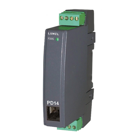
- Page 4 Rys 3. Widok separatora P20G Potwierdzenie komunikacji separatora z programatorem PD14 sygnali- zowane jest przez krótkie wygaszenie diody stanu Do konfiguracji separatora P20G przeznaczone jest oprogramowanie eCon dostępne na stronie producenta: www.lumel.com.pl. 4. DANE TEChNICZNE SEPArATOrA P20G Parametry podstawowe: –...
- Page 5 – moc pobierana < 2 VA – czas wstępnego wygrzewania separatora: 10 min – czas odpowiedzi separatora ³ 0,1 s Znamionowe warunki użytkowania: – napięcie zasilania zależne od kodu wykonań: 85...253 V a.c./d.c. 20...85 V d.c., 20...65 V a.c. – częstotliwość napięcia zasilania a.c.: 45...65 Hz –...
- Page 6 Gwarantowana dla minimalnej szerokości zakresów wyjściowych: 16 mA lub 5 V (patrz tab. 3) Wykonanie na napięcie zasilania 230 V Aktualne edycje norm znajdują się w deklaracji zgodności. 5. KOD WYKONAÑ Kod wykonań separatora P20G Tab.2. PRZETWORNIK P20G - XX XX Rodzaj zaprogramowanego wejścia:...
- Page 7 Kodowanie rodzaju wejścia i wyjścia separatora P20G Tab.3. Zakres Kod wejœcia Kod wyjscia 0...1 V 0...5 V 0...10 V 1 V 5 V 10 V 0...5 mA 0...20 mA 5 mA 20 mA 4...20 mA Wykonanie specjalne klasa przetwarzania >...
-
Page 8: Operational Safety
1. OPErATIONAL SAFETY In the safety service scope, the transducer meets to requirements of the EN 61010-1 standard. Observations Concerning the Operational Safety · All operations concerning transport, installation, and commissioning as well as maintenance, must be carried out by qualified, skilled personnel, and national regulations for the prevention of accidents must be observed. -
Page 9: Installation
2. INSTALLATION 2.1. Fitting Way P20G transducers are designed to be mounted on a 35 mm rail accor- ding to EN 60715. Overall dimensions and fitting way are shown on the fig. 1. Fig. 1 Overall dimensions and the separator fitting way. -
Page 10: External Connection Diagrams
Fig. 3. View of the P20G separator. Confirmation of the separator’s communication with PD14 programmer is indicated by the status diode which turns off for short period of time. To configure P20G separator is designed eCon software available on the web site: www.lumel.com.pl. -
Page 11: Technical Data
4. TEChNICAL DATA Basic parameters: – analog output galvanicaly isolated: - current (max. range) - 20...20 mA - voltage (max. range) -10...10 V £ 500 W - load resistance of the current output - load resistance of the voltage output ³ 500 W –... -
Page 12: Order Codes
Guaranteed for a minimal width of output ranges: 16 mA or 5 V (see table 3) Execution for 230 V supply voltage Current standard editions are in the conformity declaration. 4. OrDEr CODES Order codes of the P20G separator Table 2 SEPARATOR P20G - XX XX Kind of programmed input: see table 3 .......... - Page 13 Coding of input and output of the P20G separator Table 3 Range Input code Output code 0...1 V 0...5 V 0...10 V 1 V 5 V 10 V 0...5 mA 0...20 mA 5 mA 20 mA 4...20 mA...
- Page 14 Rys. 2. Schemat podłączeń elektrycznych separatora P20G...
- Page 15 Fig. 2. Electrical connection diagrams of the P20G separator...
- Page 16 LUMEL S.A. ul. Sulechowska 1, 65-022 Zielona Góra, Poland tel.: +48 68 45 75 100, fax +48 68 45 75 508 www.lumel.com.pl Informacja techniczna: tel.: (68) 45 75 306, 45 75 180, 45 75 260 e-mail: sprzedaz@lumel.com.pl Realizacja zamówień: tel.: (68) 45 75 207, 45 75 209, 45 75 218, 45 75 341 fax.: (68) 32 55 650...
Need help?
Do you have a question about the P20G and is the answer not in the manual?
Questions and answers