Table of Contents
Advertisement
Available languages
Available languages
Quick Links
PRZETWORNIK PARAMETRÓW OBWODÓW
PRĄDU STAŁEGO
TRANSDUCER OF DIRECT CURRENT
NETWORK PARAMETERS
P30H
INSTRUKCJA OBSŁUGI - SZYBKI START
PL
USER'S MANUAL - QUICK START
EN
Zeskanuj mnie
Zeskanuj kod
Scan the code
Pełna wersja instrukcji dostępna na
Full version of user's manual available at
www.lumel.com.pl
Advertisement
Table of Contents

Related Manuals for Lumel P30H


Summary of Contents for Lumel P30H
- Page 1 PRZETWORNIK PARAMETRÓW OBWODÓW PRĄDU STAŁEGO TRANSDUCER OF DIRECT CURRENT NETWORK PARAMETERS P30H INSTRUKCJA OBSŁUGI - SZYBKI START USER’S MANUAL - QUICK START Zeskanuj mnie Zeskanuj kod Scan the code Pełna wersja instrukcji dostępna na Full version of user’s manual available at...
- Page 2 1. WYMAGANIA PODSTAWOWE I BEZPIECZEŃSTWO UŻYTKOWANIA W zakresie bezpieczeństwa użytkowania odpowiada wymaganiom normy PN-EN 61010-1. Uwagi dotyczące bezpieczeństwa: • Montażu i instalacji połączeń elektrycznych powinna dokonać osoba z uprawnieniami do montażu urządzeń elektrycznych. • Przed włączeniem przetwornika należy sprawdzić poprawność połączeń.
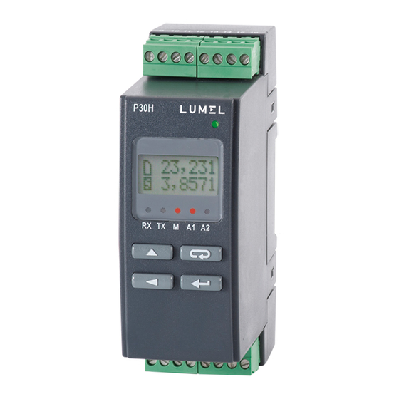
- Page 3 Rys.1. Gabaryty i sposób mocowania przetwornika. 2.2. Schematy podłączeń zewnętrznych Schematy podłączeń przedstawiono na rys. 2, na stronie 41. 3. OBSŁUGA 3.1 Opis płyty czołowej przetwornika P30H P30H P30H 230,00 230,00 Rys.3. Opis płyty czołowej przetwornika.
- Page 4 (wskaźnik zasilania), przetwornik wyświetla typ, aktualną wersję programu oraz numer seryjny. Jeżeli przetwornik został wyposażony w interfejs Ether- net (P30H-XX2XXXXXXX) po wyświetleniu numeru seryjnego przetwor- nik wyświetli jeszcze informację o zapisanym w pamięci lub otrzymanym od serwera DHCP adresie IP.
- Page 5 Wyświetla wartość mierzoną na gór- nym wierszu wyświetlacza oraz informacje dodatkowe na dolnym wierszu wyświetlacza (pkt.5.5.4 -patrz pełna wersja instrukcji obsługi, dostępna na www.lumel.com.pl). Na wskaźniku diodowym sygnalizowany jest stan transmisji na łączu RS-485, stan zajętości wewnętrznej pamięci oraz stany alarmów.
- Page 6 - przycisk rezygnacji • wejście do menu podglądu parametrów przetwornika (przytrzymanie przez około 3 sekundy), • wyjście z menu podglądu parametrów przetwornika, • zmiana treści wyświetlanej na dolnym wierszu wyświetlacza • rezygnacja ze zmiany parametru, • bezwzględne wyjście z trybu programowanie (przytrzymanie przez około 3 sekundy), •...
- Page 7 • wymuszenie rozpoczęcia przepisywania archiwum z pamięci wewnętrznej do pamięci systemu plików – dla wykonań przetworni- ka z interfejsem Ethernet; operacja ta pozwala na pobranie z prze- twornika plików z aktualnymi danymi archiwum poprzez protokół FTP. - przytrzymanie około 3 sekund, kasowanie warto- ści ekstremalnych Wciśnięcie i przytrzymanie około 3 sekund przycisku powo-...
- Page 8 3.3.3. Matryca programowania Rys.6. Algorytm obsługi przetwornika P30H...
- Page 9 3.4. Programowanie parametrów przetwornika Naciśnięcie przycisku i przytrzymanie go przez około 3 sekundy powoduje wejście do matrycy programowania. Jeżeli wejście jest zabezpieczone hasłem wówczas wyświetlony zo- stanie komunikat o konieczności wpisania hasła. Jeżeli wpisane zosta- nie niepoprawne hasło wyświetlony zostanie komunikat Zly kod.
- Page 10 Zakr.Nap Usr.PIU Kierun.I Usredn. Kasow.En Wybór zakre- Sposób Programowa Czas su pomiaru uśredniania możliwość Kasowanie uśredniania napięcia 12 wartości odwrócenia liczników wartości Ustawien / 48 / 100 / średnich P, kierunku energii chwilowych Wejscie 250 V I, U prądu U pierw.
- Page 11 CzasDel Pom.Temp Kas. Syn.Czas Reset AV Wybór Czasu Wybór Wybór czasu dla Restart zlicza- sposobu Kasowanie synchroni- wskazywa- nia wartości uzyskania licznika zacji licznika nia delty uśrednionych wartości czasu czasu napięć i temperatury prądów OpoPonA1 PodSygA1 OpoWylA1 Opóźnienie Opóźnienie ponow- Podtrzyma- wyłączenia...
- Page 12 WielkAn1 Ustawien PktDoWe1 PktGoWe1 PktDoWy1 PktGoWy1 Wyjscie Typ wielk. sterującej Dolny próg Górny próg Dolny próg Górny próg wyjściem wejścia Parametry wejścia nr 1 wyjścia nr 1 wyjścia nr 1 analogowym nr 1 wyjścia nr 1 (parametry wyjścia ana- logowego nr 2 dostępne WielkAn2...
- Page 13 Parametry dostępne tylko jeżeli włączona opcja Przekro1 WarDoWy1 WarGoWy1 PrzGoWy1 Wartość PrzDoWy1 Wartość oczekiwana oczekiwana na wyjściu Przekrocze- Przekrocze- na wyjściu przy prze- nie górne przy prze- kroczeniu -nie dolne wyjścia kroczeniu górnym wyjścia nr 1 nr 1 dolnym wyjścia nr 1 wyjścia nr 1 Parametry dostępne tylko jeżeli włączona opcja Przekro2...
- Page 14 Maska 32 AdrIP 32 AdrIP 10 Maska 10 DHCP B3,B2 bajt B1,B0 bajt B3,B2 B1,B0 bajt Włączenie/ adresu IP adresu IP bajt maski maski pod- wyłączenie (IPv4) (IPv4) podsieci sieci klienta Ustawien DHCP Ethernet uzyskane z DHCP lub wprowadzone ręcznie gdy DHCP wyłączone, il.p.TCP CzasMbus Parametry...
- Page 15 brama 32 MAC 54 MAC 32 Brama 10 MAC 10 B1,B0 bajt B1,B0 bajt B3,B2 bajt B5,B4 bajt B3,B2 bajt adresu adresu adresu bramy adresu MAC adresu MAC bramy MAC prze- domyślnej przetwornika przetwornika domyślnej twornika format: B3.B2.B1.B0 format : B5:B4:B3:B2:B1:B0 Port FTP PortHTTP...
-
Page 16: Dane Techniczne
3.4.2. Zmiana wartości zmiennoprzecinkowych Zmiana wykonywana jest w 3 etapach (przejście do następ- nego etapu następuje po wciśnięciu przycisku • ustawienie pozycji kropki (00000., 0000.0, 000.00, 00.000, 0.0000); przycisk przesuwa kropkę w lewo, natomiast przy- cisk przesuwa kropkę w prawo. Wciśnięcie przycisku w trakcie zmiany wartości parametru spowoduje zrezyg- nowanie z zapisu. - Page 17 Licznik czasu 0...999999999 s 1s/ 24h, 0...277777.5 rozdziel- t[s] czość 1 s t[H.M] Pojemność -49 999 999 … 49 999 999 kAh 0,5 % -60…180 kW -75…225 kW -60…720 kW -150…864 kW 0,4 + -0,075…1,5 klasa -0,15…1,8 MW 100V bocznika -0,075…3,75 -0,15…4,5 MW 250V...
- Page 18 Wyjścia: Wyjście analogowe główne WYJ1 analogowe, programowalne, izolowane galwanicznie * prądowe IOUT = 0/4...20 mA, rezystancja obciążenia ≤ 500 Ω; * napięciowe UOUT 0...10 V, rezystancja obciążenia ≥ 500 Ω, klasa wyjścia analogowego: 0,1; czas przetwarzania < 200 ms przeciążalność1,2 I 1,2 U OUT, Wyjście analogowe dodatkowe (WYJ2, zamiennie z wyjściem...
- Page 19 Pobór mocy < 5 VA Masa < 0,25 kg Wymiary 120 x 45 x 100 mm Mocowanie szyna 35 mm wg PN-EN 60715 Zapewniony stopień ochrony przez obudowę od strony obudowy (wykonanie bez obsługi kart SD/SDHC) IP40 od strony obudowy (wykonanie z obsługą kart SD/SDHC) IP30 od strony zacisków IP20 Pole odczytowe: tekstowy wyświetlacz LCD 2x8 znaków z podświet- leniem LED...
- Page 20 – posobnika D5) - podstawowa pomiędzy wszystkimi pozostałymi obwodami (1min / 2.21kV d.c.), za wyjątkiem wykonań: P30H-X2X2XXXXX – izolacja pomiędzy wyjściem zasilającym 24V d.c. (zaciski 11,12) a gniazdem Ethernetu podstawowa (60s /1,4 kV a.c.) kategoria instalacji - III dla napięć...
- Page 21 - II dla napięć wejściowych z zakresu 600...1000 V d.c., (pomiar z wykorzystaniem dodatkowego zewnętrznego rezystora – posob- nika D5); stopień zanieczyszczenia 2, maksymalne napięcie pracy względem ziemi: 300 V dla obwodu za- silania i obwodów pomiarowych, 50 V dla pozostałych obwodów wysokość...
-
Page 22: Basic Requirements, Operational Safety
1. BASIC REQUIREMENTS, OPERATIONAL SAFETY The transducer meets the requirements of EN 61010-1 standard in terms of operational safety. Safety precautions: • The assembly and installation of electrical connections must be carried out by a person authorized to install electrical equipment. •... -
Page 23: External Connections Diagrams
Lock Fig.1. Overall dimensions and method of mounting the transducer. 2.2. External connections diagrams Connection diagrams are presented on fi g.2, on page 41. 3. OPERATION 3.1 P30H transducer front panel description P30H P30H 230,00 230,00 Fig.3. Front panel description... -
Page 24: Messages After Switching On The Power
LED (power indicator) on, transducer displays the type, current software version and the serial number. If the transducer is equipped with Ethernet interface (P30H-XX2XXXXXXX), then after displaying the serial no., the device displays also the IP address saved in memory or received from DHCP server. - Page 25 3 seconds. Measured value is displayed in the upper line of the display, the additional information is displayed in the lower line (see 5.5.4 - full version of user’s manual, available at www.lumel.com.pl). LED display shows the RS-485 transmission status, internal memory usage and alarm status.
-
Page 26: Functions Of Key Combinations
• turning the transducer on and holding down the button - entering into software update mode via RS-485 interface, the link parameters: baud rate 115200 bit/s, 8N2 mode. - cancel key • enters the transducer parameter display mode (hold the button for at least 3 seconds), •... - Page 27 - hold for about 1 second • force start copying the archive from the internal memory into SD/SDHC memory card – transducer equipped with an external SD/SDHC memory slot • force start copying the archive from the internal memory to the fi le sy- stem memory –...
-
Page 28: Programming Matrix
3.3.3. Programming matrix Fig. 4. P30H operation algorithm... -
Page 29: Programming Transducer Parameters
3.4. Programming transducer parameters Press and hold for about 3 seconds key to enter the programming matrix. If access is password protected, transducer will ask for password. If the entered password is incorrect, Err.Code message will displayed. Correct password enables cess to the programming matrix. - Page 30 VoltRang DemandTm I direct Averag. Clear En range of method of Program Averaging voltage mea- averaging possibility time of in- Clear energy surement 12 the mean to reverse stantaneous counter Settings / 48 / 100 / values P, the current values Input 250 V...
- Page 31 DeltTime TempMeas Reset AV Syn.Time Selecting The choice Rst.Coun Restart Selection the time to of how counting of timer indicate the to obtain Timer reset the average synchroni- delta vol- temperature values zation tages and values currents SgKeepA1 DlyOffA1 OnLockA1 Alarm 1 Alarm 1...
- Page 32 Settings ParamAn1 AnIn Lo1 AnIn Hi1 AnOutLo1 AnOutHi1 Output Control value of analog Input 1 Input 1 upper Output 1 Output 1 Output output 1 lower limit limit lower limit upper limit parameters type (analog output #2 parameters availab- le only ParamAn2 when the...
- Page 33 Parameters available only when the OverSer1 option is on OvrOutL1 OvrOutH1 OverSer1 OvOutHi1 Output 1 Output 1 expected expected va- Enabling an Output 1 value lue when the overrun of upper limit when the upper limit is output 1 overrun lower limit is exceeded...
- Page 34 mask 32 addrIP32 addrIP10 mask 10 DHCP B3,B2 byte of IP B1,B0 byte of B3,B2 byte B1,B0 byte Enable/di- address IP address of the subnet of the subnet sable DHCP (IPv4) (IPv4) mask mask client Settings Ethernet uzyskane z DHCP lub wprowadzone ręcznie gdy DHCP wyłączone, no.c.TCP Ethernet AddrmTCP...
-
Page 35: Changing The Value Of The Selected Parameter
gate 32 MAC 54 MAC 32 gate 10 MAC 10 B1,B0 B3,B2 byte B5,B4 byte B3,B2 byte byte of the B1,B0 byte of the default of the trans- of the trans- default of the trans- gateway ducer MAC ducer MAC gateway ducer MAC address... -
Page 36: Changing Fl Oating-Point Values
3.4.2. Changing fl oating-point values The change is carried out in 3 stages. (the transition to the next stage follows after pressing the key. • setting the dot position (00000., 0000.0, 000.00, 00.000, 0.0000); key moves the dot to the left, and key mo- ves the dot to the right. - Page 37 Timer 0...999999999 s 1s/ 24h, 0...277777.5 resolution t[s] t[H.M] Capacity -49 999 999 … 49 999 999 kAh 0.5 % -60…180 kW -75…225 kW -60…720 kW -150…864 kW 0.4 + -0.075…1.5 shunt -0.15…1.8 MW 100V class -0.075…3.75 Power -0.15…4.5 MW 250V P, P 0.4 +...
- Page 38 Outputs: Main analog output OUT1 analog, programmable, galvanically isolated * current I = 0/4...20 mA, load resistance ≤ 500 Ω; or * voltage U 0...10 V, load resistance ≥ 500 Ω, analog output class 0.1; processing time < 200 ms overload: 1.2 I or 1.2 U Additional analog output (OUT2, interchangeably with relay output)
- Page 39 Noise emission acc. to EN 61000-6-4 Safety requirements: according to EN 61010-1 standard isolation between circuits (P30H-X0XXXXXXX, P30H-X1XXXXXXX): increased between input circuits (terminals 1-4) and remaining circuits (60s/3.51 kV a.c.) for input voltages up to 300 V d.c. basic between input circuits (terminals 1-4) and remaining circuits (60s/3.51 kV a.c.) for input voltages from the range 300...1000 V...
- Page 40 300...1000 V d.c. (measurement with use of additional resistor basic between all remaining circuits (1 min/2.21 kV d.c.) ), save for ordering version: P30H-X2X2XXXXX– isolation between power output 24 VDC (terminals 11, 12) and Ethernet slot (60s/1.4 kVAC) Installation categorie III for input voltage up to 300 V d.c.,...
- Page 41 SCHEMATY PODŁĄCZEŃ ELECTRICAL CONNECTIONS Prąd, Napięcie, pomiar pośredni z wykorzysta- pomiar bezpośredni niem bocznika zewnętrznego 12 V, 48 V, 100 V, 250 V na wej. +/- 150 mV Voltage Current, direct measurement indirect measurment using 12 V, 48 V, 100 V, 250 V external shunt on input.
- Page 42 If you need to measure voltages higher than 300V d.c., must use an external addi- tional resistor type D5 / 1 (600V) or D5 / 2 (1000V) For the measured voltage range 300...600V P30H set with additional resistor D5 meets the requirements:...
- Page 43 RS-485 WEJŚCIE/ INPUT measuring input 1 2 3 4 5 6 7 1 2 3 4 5 6 7 8 RS-485 - interfejs/ interface RS-485 P30H-XXX21XXXXX P30H-XXX11XXXXX WYJ/OU 3 WYJ/OU 2 WYJ/OU 3 WYJ/OU 2 WYJ/OU 2 - wyj.analog.nr 2, 0/4..20 mA WYJ/OU 2 - wyj.analog.nr 2, 0/4..20 mA...
- Page 44 LUMEL S.A. ul. Słubicka 4, 65-127 Zielona Góra, Poland tel.: +48 68 45 75 100, fax +48 68 45 75 508 www.lumel.com.pl Informacja techniczna: tel.: (68) 45 75 140, 45 75 141, 45 75 142, 45 75 145, 45 75 146 e-mail: sprzedaz@lumel.com.pl...
Need help?
Do you have a question about the P30H and is the answer not in the manual?
Questions and answers