Table of Contents
Advertisement
Quick Links
Advertisement
Table of Contents

Subscribe to Our Youtube Channel
Related Manuals for Lumel P30H


Summary of Contents for Lumel P30H
- Page 1 TRANSDUCER OF DIRECT CURRENT NETWORK PARAMETERS P30H USER’S MANUAL...
-
Page 2: Table Of Contents
4. Installation..............................7 4.1. Mounting............................7 4.2. External connection diagrams......................8 5. Service..............................10 5.1. Description of P30H transducer's frontal plate.................10 5.2. Power-on messages........................11 5.3. Functions of the buttons........................12 5.3.1. Functions of single buttons........................12 5.3.2. Functions of button combinations......................14 5.3.3. - Page 3 P30H-09B User's manual 5.10.4 Modbus TCP/IP...........................112 6. Accessories............................112 6.1. Memory card..........................112 6.2. Additional resistor D5......................... 113 7. Error codes............................116 8. Technical data............................ 117 9. Ordering code............................ 123...
-
Page 4: Application
P30H-09B User's manual 1. Application Programmable transducer P30H is suited for voltage, current (voltage measurement from a shunt) and power measurement in d.c. circuits and for conversion of measured value into a standard d.c. and a.c. signal. Output signal is galvanically insulated from input signal and power signal. - Page 5 P30H-09B User's manual ●compatibility with RS-485 interface with MODBUS protocol, in RTU mode, ●measurement averaging time programming, ●SD/SDHC card use – FAT and FAT32 system compatibility, ●Master RS-485 mode – 1 device query, ●Ethernet interface10/100 BASE-T (optional) ◦protocol: Modbus TCP/IP, HTTP, FTP, ◦services: web server, FTP server, DHCP client...
-
Page 6: Transducer Set
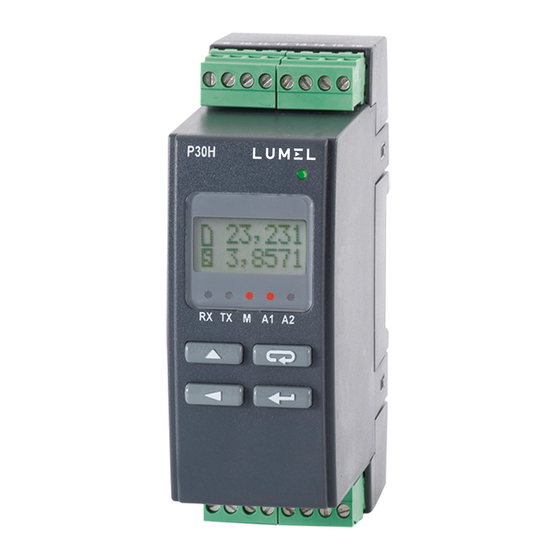
P30H-09B User's manual Fig. 1 Appearance of P30H transducer different versions. 2. Transducer set ●P30H Transducer 1 pc ●user's manual 1 pc ●warranty card 1 pc ●plug with the screw terminals 2 pc 3. Basic requirements, operational safety In the security scope, the transducer meets the requirements of the EN 61010-1 standard. - Page 7 P30H-09B User's manual ●Always check the connections before turning the transducer on. ●The transducer is designed to installation and usage in the industrial electromagnetic environment. ●A switch or a circuit-breaker should be installed in the building or facility. It should be located near the device, easily accessible by the operator, and suitably marked.
-
Page 8: Installation
P30H-09B User's manual 4. Installation 4.1. Mounting The P30 transducer are designed for installation on a 35 mm rail acc. to EN 60715. Overall dimensions and mounting is shown in Figure 2. Fig.2 Overall dimensions and mounting of the transducer. -
Page 9: External Connection Diagrams
P30H-09B User's manual 4.2. External connection diagrams... - Page 10 If you need to measure voltages higher than 300V d.c., must use an external additional resistor type D5 / 1 (600V) or D5 / 2 (1000V) For the measured voltage range 300...600V P30H set with additional resistor D5 meets the requirements: - CAT III, - basic isolation between input circuits (terminals 1-4) and other circuits ( 60s /3,51kV a.c.
-
Page 11: Service
P30H-09B User's manual 5. Service 5.1. Description of P30H transducer's frontal plate Fig.4 Description of the transducer's frontal plate Note: Memory card (optional) should be inserted into the transducer with contacts on the bottom side. Description of LED indicator: RX – green LED - indicator of data receiving on RS-485 link TX –... -
Page 12: Power-On Messages
LED (power indicator) on, transducer displays the type, current software version and the serial number. If the transducer is equipped with Ethernet interface (P30H-XX2XXXXXXX), then after displaying the serial no., the device displays also the IP address saved in memory or received from DHCP server. -
Page 13: Functions Of The Buttons
P30H-09B User's manual measurement and processing the analog output signal after approx. 3 seconds. Measured value is displayed in the upper line of the display, the additional information is displayed in the lower line, see 5.5.4). LED display shows the RS-485 transmission status, internal memory usage and alarm status. - Page 14 P30H-09B User's manual - digit change button ●change of the displayed value ●moving to the parameter group level, ●navigation within selected level ●selected parameter value change – moving to subsequent number ●turning the transducer on and holding down the button - entering into software update mode via RS-485 interface, the link parameters: baud rate 115200 bit/s, 8N2 mode.
-
Page 15: Functions Of Button Combinations
P30H-09B User's manual 5.3.2. Functions of button combinations - holding down for approx. 3 second ●deletes alarm signalization; this operation works only with support function turned on; - holding down for approx. 1 second ● displays maximum of the currently displayed value - holding down for approx. -
Page 16: Programming Matrix
P30H-09B User's manual Pressing and holding the button for approx. 3 seconds causes exiting to the programming matrix. The programming matrix can be protected by an access code. 5.3.3. Programming matrix Fig. 7 P30H Transducer service algorithm... -
Page 17: Programming Parameters Of The Transducer
P30H-09B User's manual 5.4. Programming parameters of the transducer Pressing the button Pressing and holding down the button for approx. 3 seconds allows to exit to the programming matrix. If the output is password-protected, a password entry message will be displayed. - Page 18 P30H-09B User's manual Settings DecimalP Bcklight Bckl.Int Display Display Minimum Time of a Intensity of parameters decimal display panel LCD display point illumination panel illumination Settings Param.A1 Type A1 OverLoA1 OverHiA1 DlyOnA1 DlyOffA1 OnLockA1 SgKeepA1 Alarm 1 Alarm 1 Input value...
-
Page 19: Type Of Selected Parameter Value Change
P30H-09B User's manual Settings DHCP addrIP32 addrIP10 mask 32 mask 10 gate 32 gate 10 MAC 54 MAC 32 MAC 10 Ethernet Ethernet Enable/dis B3,B2 byte B1,B0 byte B3,B2 byte B1,B0 B3,B2 B1,B0 B5,B4 byte B3,B2 byte B1,B0 byte interface... -
Page 20: Changing The Floating-Point Values
P30H-09B User's manual 5.4.2. Changing the floating-point values The change is done in 3 stages (to move to a next stage press the following button: ●setting the decimal point (00000., 0000.0, 000.00, 00.000, 0.0000); button moves the point to the left, while button moves point to the right. - Page 21 P30H-09B User's manual synchronized with the clock, the time aggregation 30 minutes The measurement 60 min synchronized with the clock, the time aggregation 60 minutes Averaging time of Averaging time 20 ms Averag. 20ms instantaneous values Averaging time200 ms 200 ms...
- Page 22 P30H-09B User's manual synchronization Timer start start Automatic timer start after synch.I the threshold of startup current CurrThrs is exeeded DeltTime Selecting the time to The time interval in indicate the delta determining the delta voltages and currents voltages and currents – 5...
- Page 23 P30H-09B User's manual Table 2 Settings Display Parameter Description Range of changes symbol Bcklight Time of a display panel On - permanently switched on illumination - permanently switched off - switched on for X seconds … Bckl.Int Intensity of LCD display...
- Page 24 P30H-09B User's manual Avarage current temperature Temper second value displayed time Clock Alarm type. Fig. 12 shows normal (change from 0 to Type A1 n-on Type A2 the rendering of the alarm types. n-off normal (change from 1 to manual off; alarm output is...
- Page 25 P30H-09B User's manual Table 4 Settings Output Parameter Description Range of changes symbol Param.A1 Input value type controlling voltage the analog output current power Delta of voltage in the time interval Delta of current in the time interval Timer in seconds...
- Page 26 P30H-09B User's manual OvOutLo1 Lower limit overrun of output 0...24000 (value x1000) OvOutHi1 Upper limit overrun of output 0...24000 (value x1000) OvrOutL1 Output expected value when 0...24000 the lower limit is exceeded (value x1000) OvrOutH1 Output expected value when 0...24000...
- Page 27 P30H-09B User's manual 115200 bit/s 115200 230400 bit/s 230400 256000 bit/s 256000 … Base.Reg Number of the base register 65536 queried/monitored in the Master or Monitor mode of RS-485 interface … No.ofVal Number of values queried in Master mode or...
- Page 28 P30H-09B User's manual 1,0,3,2) slng2x16 Register type swapped long, value in two 16-bit registers (32 bits signed, byte sequence 3,2,1,0) ulng2x16 Register type unsigned long, value in two 16-bit registers (32 bits unsigned, byte sequence 1,0,3,2) uSln2x16 Register type unsigned...
- Page 29 P30H-09B User's manual Mast.Fun Modbus protocol function fun.0x03 Function 0x03 used by the transducer fun.0x04 Function 0x04 working with RS-485 interface in Master mode No.OfErr Maximum allowed number of 0...10 repeated queries for the transducer with RS-485 interface in Master mode...
- Page 30 Ar. Time Archiving period (s) 1...3600 Ar.Erase Deleting an internal archive deleting an internal archive do nothing Rec.ToSD Forced rewriting of the rewriting of the internal archive contents from archive to the SD/SDHC internal memory to external card SD/SDHC card (type: P30H- do nothing...
- Page 31 P30H-X2XXXXXX) … Param.SD The percentage of the internal archive space used which triggers automatic writing to SD/SDHC card Table 7 Settings Ethernet (option, only type P30H-XX2XXXXXX) Parameter Description Range of changes symbol Enabling/disabling the DHCP DHCP disabled - you DHCP...
- Page 32 P30H-09B User's manual decimal format, IPv4 address format: B3.B2.B1.B0 … Third and second byte mask 32 000.000 255.255 (B3.B2) of the transducer subnet mask, a value is displayed in decimal format, mask format: B3.B2.B1.B0 … First and zero byte (B1.B0) mask 10 000.000...
- Page 33 P30H-09B User's manual … TimeMbus Port closing time of Modbus TCP/IP service, in seconds … no.c.TCP The maximum simultaneous connections to Modbus TCP/IP service p.komFTP FTP server commands port 20...65535 number FTP port FTP server data port number 20...65535 PortHTTP Web server port number 80...65535...
-
Page 34: Functions Of The Transducer
P30H-09B User's manual Entered value will not be used. Date setting - month+day. Date 01-01-10...31-12-99 Entering invalid date value cancels date setting. Entered value will not be used. Automatic DST and no automatic daylight AutoCzas inversely saving time change with automatic daylight... -
Page 35: Mean Values, Synchronized With The Clock
P30H-09B User's manual second fir P30H transducer. This time can be changed to one of the predefined values: 0.02, 0.2, 0.5, 1, 3, 5, 10 seconds. Instantaneous values include: voltage, current (registers 7500...7507). 5.5.1.2 Mean values, synchronized with the clock For the values of active power, apparent power and current (registers 7508..7510) an averaging function for the period of 15, 30... -
Page 36: Transducer Configuration Example For Control Of Charging Lead Acid Battery
5.5.1.4. Transducer configuration example for control of charging lead acid battery Schematic below illustrates connection of P30H transducer used for control of charging process of lead acid battery with nominal voltage of 12V and capacity of 60Ah, with the use of the external DC voltage source. - Page 37 = 0,15V/5,4A = 0,0277 W » 0,02 W, - the shunt shunt shunt initial max should be 0,02 W (or less) Configuration of P30H transducer: The circuit will be controlled with the usage of alarm relay no. 1 (stopping the loading process when the 14,4V threshold is met) Register Parameter...
- Page 38 P30H-09B User's manual 4003 Averaging time of Averag. 10 s instantaneous values 4004 Synchronization of Syn.Time Synch. I timer with value of charging current 0,05 7619 Current threshold CurrThrs 0,05 above which time is counted 4005 Normal direction of I direct Normal.
-
Page 39: Analog Outputs
- after saving the parameter the register value will automatically set to "0" 5.5.2. Analog outputs P30H transducer is always equipped with one main analog output (output #1) for current (source) or voltage, depending on the version. Output is connected to the terminals 15 and 16. Depending on... -
Page 40: Analog Outputs Overrun Support
Fig.10 Individual characteristic of analog output 5.5.2.2 Analog outputs overrun support P30H transducer allows the user to configure the analog outputs to handle the overrun of the defined threshold values. Overrun support is disabled by default – in such case, after the value controlling the output is overrun, the output is still controlled proportionally to the controlling value outside the basic output range. - Page 41 P30H-09B User's manual Table 9 Register Parameter Register Parameter value symbol in the value symbol in the menu menu 4100 ParamAn1 4101 OverSer1 7606 -200 AnIn Lo1 -200.0 7607 1200 AnIn Hi1 1200.0 7608 4000 AnOutLo1 4000 7609 20000 AnOutHi1 20000 value in the register is an integer value multiplied by 1000 (4mA →...
- Page 42 P30H-09B User's manual If the overrun support is turned on with all remaining values unchanged (parameters set according to Tab. 10), then the analog output will react as shown in the Fig. 11. Table 10 Register Parameter Register Parameter value...
- Page 43 P30H-09B User's manual Example: Main analog output (no. 1) configuration for the time reaction Individual characteristics of the analog output no. 1 (current) are set so that the output reacts to the real time (hour*100+minute), i.e. for the 00:00 hours, the expected value is 4 mA and for 23:59 hours, the...
-
Page 44: Alarm And Power Outputs
User's manual 5.5.3 Alarm and power outputs P30H transducer can be equipped with 2 normally open alarm contacts or 1 output with normally open contact and 1 24 VDC power output. (depending on version) Each alarm (24 VDC power output should be treated like one) can operate in one of six available modes. -
Page 45: Lcd Display
AL_L > AL_H value will disable the alarm. 5.5.4 LCD display P30H transducer is equipped with illuminated LCD display with two lines, 8 characters each. Upper display line is used to show values displayed in float format (5 digits for the value < 1000.0 or 4 digits + magnitude symbol for values 1000.0) and to display status icons of the... - Page 46 ●vvvvvG – overrun of the lower range limit for the value displayed G – overrun of the upper range limit for the value displayed ● Lower line of the P30H transducer display can perform several functions. Pressing the following button: cycles the functions of the lower display line: ●name of the displayed value complete with the unit and the internal...
- Page 47 P30H-09B User's manual 27,532 27,532 18:23:35 27,532 05-07-11 27,532 27,532 0,0000 Fig. 14 Graph showing the cycling of the lower display line information.
- Page 48 P30H-09B User's manual 70,325 0,3256 24,548 22,856 (when temperature measurement (when temperature (gdy włączony (gdy włączony pomiar temperatury) pomiar temperatury) measurement on 0,3256 245,5k 5,455k 0,0000 dU V (when (gdy wyłączony pomiar temperatury) temperature measurement off) 22,856 22,856 dI A...
- Page 49 P30H-09B User's manual Timer in seconds Timer in hours, minutes t H,M Capacity C Ah Avarage power PAV W Avarage voltage UAV V Avarage current IAV I Temperature (option) Imported energy Exported energy Sum of energy (imported and exported) Difference of energy (imported...
-
Page 50: Saving And Reading Transducer Configuration File
SD/SDHC card or file system internal memory. Configuration file should be located in the P30H folder and be named P30H_PAR.CON. File can be generated by properly configured P30H transducer or by the eCon... - Page 51 TCP/IP). For P30H transducers in P30H-X2XXXXXX version, file can be transferred between devices via FTP. For P30H transducers in P30H-X1XXXXXX version, single file on a memory card can be used to configure several transducers equipped with SD card slot. To force parameter update from the file, power the transducer on while holding the following button: .
-
Page 52: Default Settings
P30H-09B User's manual 5.6. Default settings Table 15 shows the standard settings of the P30D transducer. These settings can be reverted via the following option in the transducer → → menu: Settings Service or via the Fabr.Par RS-485 interface after entering value “1” into register 4055. - Page 53 P30H-09B User's manual DlyOffA1 DlyOffA2 OnLockA1 OnLockA2 SgKeepA1 SgKeepA2 Param.A1 Param.A2 AnIn Lo1 AnIn Lo2 AnIn Hi1 AnIn Hi2 AnOutLo1 AnOutLo2 AnOutHi1 AnOutHi2 OverSer1 OverSer2 OvOutLo1 OvOutLo2 4000 OvOutHi1 OvOutHi2 20000 OvrOutL1 OvrOutL2 4000 OvrOutH1 OvrOutH2 20000 Address ModeUnit r8n2...
- Page 54 P30H-09B User's manual Undefined Date AutoTime DispTest Polish (for Language versions P30H- XXXXXXXXPX English (for versions P30H- XXXXXXXXEX) SaveFile , (for versions Separat. P30H- XXXXXXXXPX) . (for versionsP30H- XXXXXXXXEX) DHCP addrIP32 192.168 addrIP10 001.030 mask 32 255.255 mask 10 255.000 Gate 32 192.168...
-
Page 55: Software Upgrades
P30H-09B User's manual 5.7. Software upgrades A feature implemented in the P30H transducers enables to upgrade firmware using a PC with eCon software installed. Free eCon software and the update files are available at www.lumel.com.pl. Upgrade is possible if a PC is connected to RS485 to USB converter, such as PD10 converter. - Page 56 P30H-09B User's manual necessary to revert them later). Next, click the Firmware update link, the LUMEL UPDATER (LU) software will appear – Fig. 24. Press the Connect button. Messages information window displays information concerning upgrade process. If the port is opened correctly, a Port opened message appears.
-
Page 57: Measuring Values Archiving
SD/SDHC card slot, allowing the archive data as files on the external SD/SDHC card. P30H-XX2XXXXXX version is equipped with 8GB internal file system memory (memory size can be increased by manufacturer or on special order) storing the data automatically rewritten from the internal... -
Page 58: Internal Memory
P30H-09B User's manual memory. The files can be downloaded via Ethernet using FTP. Caution: Changing the menu parameter value Archive → will result in erasing the internal memory Arch.Val archive!!! 5.8.2 Internal memory Transducer internal memory is divided into 8192 pages. Every memory page can accommodate up to 66 data records. -
Page 59: Structure Of The Record
P30H-09B User's manual indicator. Table 16 describes the internal memory fill indicator. Table 16 Symbol Internal memory fill percentage 5.8.2.1 Structure of the record All data written to the internal data memory are stored as 8-byte records. Structure of the record is presented in the table below. -
Page 60: Acquisition Of Archived Data From The Internal Memory
P30H-09B User's manual Table 18 Register HEX value 4553 0x0170 4554 0xBB95 4555 0xE87C 4556 0xB942 rec = 0x0170BB95E87CB942 Data = 0xE87CB942 → (float) → 92.743958; Table 19 Registration time = 0x0170BB95 → b1011100001011101110010101 Year + 2010 Month Hour Minute... - Page 61 P30H-09B User's manual insert the SD/SDHC card into the slot (contacts side down), making sure that the card was successfully mounted (a following card icon is displayed in the upper left corner of the display: ). It is necessary to set the percentage fill threshold, because after this value is reached, the data will be automatically saved to card of file system internal memory –...
-
Page 62: Archiving Configuration
P30H-09B User's manual following the combination of buttons: and connect the transducer to FTP client again. 5.8.3 Archiving configuration Archiving parameters can be configured via the registers 4064 – 4069 (Tab. 37) and transducer menu in the Settings → Archive group. -
Page 63: Memory Card Or Internal Memory File System (Optional)
– memory size 8GB. It is compatible with both FAT and FA32 file systems. If the memory card is not formatted, it should be formatted in the card reader from the PC level. P30H transducer creates directories and files containing archive data. Before the card is inserted in the transducer, make sure that the card is not write-protected. - Page 64 P30H-09B User's manual unmounted (see sec. 5.3.2) – the card is unmounted by pressing the buttons . Removal of the card that was not unmounted may corrupt the card contents. Memory card status is described in the transducer registers (sec. 5.9.8. Tab. 42). After the card is inserted into...
- Page 65 P30H-09B User's manual P30H transducer creates directories and files on the card during registration. An example of the directory structure is shown in Figure 20. Fig. 20 The directory structure on the SD card. Besides the ARCH directory, holding the archived data, a SYSTEM directory is created on the card and complete with the file start.txt holding the date and hour of the installation of card or file...
-
Page 66: Archive Files Structure
Service menu or entering value “1” into register 4070; archived values are written in the engineering format 5.9. RS-485 interface Programmable digital P30H transducers are equipped with serial RS-485 link for communication with computer systems and other Master devices. Asynchronous character MODBUS communication... -
Page 67: Connection Of The Serial Interface
9600 b/s). It is necessary to use additional intermediate-separation circuits for connecting higher number of the devices, for example PD51 manufactured by LUMEL S.A. Output of the interface line is shown in Fig. 3. To obtain the correct transmission it is necessary to connect the lines A and B in parallel with their equivalents in other devices. -
Page 68: Description Of The Modbus Protocol Implementation
5.9.2 Description of the MODBUS protocol implementation The implemented protocol is compliant with the PI-MBUS-300 Rev G specification of Modicon. Overview of P30H transducer MODBUS protocol serial port parameters: ●Transducer address 1..247. ●Baud rate: 4800, 9600, 19200, 38400, 57600, 115200, 230400, 256000 [b/s]. -
Page 69: Description Of The Implemented Functions
●Identical baud rate and a type of transmission mode 5.9.3 Description of the implemented functions The following functions of the MODBUS protocol have been implemented in P30H transducers: ●03 (03h) – readout of registers group ●04 (04h) – readout of input registers group ●06 (06h) –... - Page 70 P30H-09B User's manual Response: Table 23 Device Number Value from the register Value from the register address Function of bytes 1DB0 (7600) 1DB1 (7601) checksu E46Fh Example 2: Readout of two 32-bit float registers (7501, 7502) as a combination of 2 x 2 16-bit registers (7002, 7003, 7004, 7005), starting with the register address 1B5Ah (7002) - 32-bit register values 25.68,...
- Page 71 P30H-09B User's manual Example 3: Readout of two 32-bit float registers (7501, 7502) as a combination of 2 x 2 16-bit registers (6002, 6003, 6004, 6005), starting with the register address 1772h (6002) - 32-bit register values 25.68, 20.25. Request:...
- Page 72 P30H-09B User's manual Response: Table 29 Device Register address Register value address Function checksum 9B94h Writing to n-registers (code 10h) Example 5: Writing two registers starting with the register address 1DB0h (7600) Writing the values 20, 200. Request: Table 30...
-
Page 73: Interface Rs-485 Master Mode
P30H-09B User's manual Response: Table 33 Addr Functi Device Device Field dependent on device Checksum status (CRC) Firmware Registers 4308,4309, 4310, 4311 v 2.00 describing serial number, and device bytes configuration of the transducer (ser. no.: 13100001) 02h 00h A0h 01h 6Ch 0Dh A0h 01h 6Ch 0Dh 69FCh Field dependent on the device –... - Page 74 P30H-09B User's manual 10 Mast.Fun Function selection for Master mode (0x03 or 0x04) 11 No.OfErr Number of query retries when no response is received Parameters 4 - 6 can also be configured via RS-485 (registers 4048-4052) before Master mode is selected. After the Master mode is selected, transducer cannot be queried by another Master device.
-
Page 75: Interface Rs-485 Monitor Mode
5.9.5 Interface RS-485 Monitor mode RS-485 interface can operate in Monitor mode, allowing for monitoring RS-485 network traffic and react to particular response register of the selected device. P30H has to share the communication parameters with monitored devices. Serial interface Monitor mode is... - Page 76 P30H-09B User's manual enabled by selecting the following mode from menu: Mbus 485 → → or entering the value “1” to register 4042. In the Mode Monitor Monitor mode, configure the following parameters in Mbus 485 menu: Table 35 Item Modbus...
-
Page 77: Map Of The Registers
Mode Slave. 5.9.6 Map of the registers In the P30H transducer, data are placed in 16-bit and 32-bit registers. Process variables and transducer parameters are placed in the register address area in a way depending on the variable value type. Bits in 16-bit registers are numbered from the youngest to the oldest (b0 …... - Page 78 P30H-09B User's manual 7000-7198 float (32 bits) Value set in the two following 16-bit registers. These registers contain the same data as 32- bit registers from 7500 range. Readout registers. Bytes sequence (B3,B2,B1,B0) 6200 - 6337 float (32 bits) Value set in the two following 16-bit registers.
-
Page 79: Registers For Writing And Readout
P30H-09B User's manual 5.9.7 Registers for writing and readout Table 37 value is Symbol Range Description located in the 16-bit registers 4000 0...3 VoltRang Value Range of voltage input 12 V 48 V 100 V 250V 4001 0...1 Timer reset Rst.Coun... - Page 80 P30H-09B User's manual 4004 0...1 Selection of timer synchronization Syn.Time Value Timer off Timer permanently on Counter tiggering with current threshold – when current value > value in register 7619 4005 0...1 Current direction I direct Value Normal Reversed 4006..
- Page 81 P30H-09B User's manual determining the delta voltages and currents – 5 s The time interval in 30 s determining the delta voltages and currents – 30 s The time interval in 1 min determining the delta voltages and currents – 1 min...
- Page 82 P30H-09B User's manual Value Description Disabled 1...60 Disabled for 1...60 s Permanently enabled 4023 RESERVED 4024 0..6553 Number of the register displayed on the Disp.Reg lower display line (to display float type register value within the 16-bit registers input corresponding number of the 32-bit...
- Page 83 P30H-09B User's manual 4030 0...900 Alarm 1 re-activation delay time (s) OnLockA1 4031 0...1 Alarm 1 signalization latch (LED flashing) SgKeepA1 Value Description Latch disabled Latch enabled 4032 RESERVED 4033 0...14 Input value controlling the alarm 2 Param.A2 Value Description Register values 7500 - voltage Register values 7501 –...
- Page 84 P30H-09B User's manual 4039... RESERVED 4041 4042 0...2 Interface RS-485 operating mode Mode The transducer serves as Slave on the RS485 line, waiting for the queries and responds if they are addressed The transducer monitors the traffic on the RS485 line and...
- Page 85 P30H-09B User's manual function 0x04 4047 0...10 Allowed number of errors in the No.OfErr RS-485 interface Master mode 4048 10...500 Maximum time until response in serial AnswTime interface Master and Monitor modes [ms] 4049 0...12 Type of values queried/monitored in serial...
- Page 86 P30H-09B User's manual 16-bit registers (32 bits unsigned, byte sequence 3,2,1,0) 4050 0...6553 Number of the base register Base.Reg queried/monitored in the RS-485 interface Master or Monitor mode 4051 0...50 Number of values queried/monitored in No.ofVal serial interface Master or Monitor mode 4052 1...3600...
- Page 87 P30H-09B User's manual 4061 2001... Current year in YYYY format. 2099 4062 0...1 Automatic DST and inversely Value Description 4063 RESERVED 4064 0... Selecting archived values Arch.Val 65535 Caution: change of register value will result in deletion of the internal memory...
- Page 88 P30H-09B User's manual Second value displayed Clock 4066 0...5 Archiving type (description – Fig. 18) Ar. Mode Value Description n-on n-off h_on h_off 4067 1...3600 10 Archiving period in seconds Ar. Time 4068 0...1 Deleting an internal archive Ar.Erase 4069 0...1...
- Page 89 P30H-09B User's manual 4079 RESERVED 4080 0...1 Setting the new parameters of Ethernet EthStdPa interface Value Description No change Restoring the default parameters of Ethernet interface 4081 0...6553 The third and the second byte (B3.B2) of addrIP32 the IP address of the transducer, the IPv4 address format: B3.B2.B1.B0...
- Page 90 P30H-09B User's manual manually configure the IP address and subnet mask of the transducer; DHCP enabled, the transducer will automatically receive the IP address, subnet mask, and gateway address from the DHCP server when switching the supply on or selecting ReInitEt option from the menu or entering the value "1"...
- Page 91 P30H-09B User's manual initiate Ethernet interface 4100 0..16 Input value controlling the analog output 1 ParamAn1 Value Description Register values 7500 - voltage Register values 7501 – current Register values 7502 – power Register values 7503 Register values 7514 -...
- Page 92 P30H-09B User's manual 4107 0...1 Analog output 2 overrun support OverSer2 Value Description 4108 0...2400 Output 2 lower overrun value x1000 OvOutLo2 4109 0...2400 Output 2 upper overrun value x1000 OvOutHi2 4110 0...2400 Output 2 expected value, when its lower...
- Page 93 P30H-09B User's manual Table 39 Value set in The value Symbol Range Description the two is located following in 32-bit 16-bit registers. registers. Registers contain the same data as 32-bit registers from the area 7600. 6200/7200 7600 OverLoA1 w/r -9.9999e13 Alarm 1 lower limit ...99999e13...
- Page 94 P30H-09B User's manual limit of the controlling value 6222/7222 7611 AnIn Hi2 w/r -9.9999e13 100 Individual characteristic of ...99999e13 analog output 2 - upper limit of controlling value 6224/7224 7612 AnOutLo2 w/r 0...24 Individual characteristic of analog output 2- lower...
-
Page 95: Registers For Readout
P30H-09B User's manual Value set in The value is Quantity name the two located in the following 16- 32-bit registers. bit registers. Registers contain the same data as 32-bit registers from the area 8000. 8100/8200 8000 The value of the 1st register readout by the... - Page 96 P30H-09B User's manual failure Bit13 29 Clock – daylight saving on/off Bit12 28 No communication with data memory Bit11 27 Invalid settings Bit10 26 Default settings restored Bit9 Bit8 24 Internal archive communication error Bit7 23 Archive parameters error Bit6...
- Page 97 P30H-09B User's manual Value Description No card The card inserted but not installed (uninstalled). Card inserted but the attempt failed. The card inserted, installed correctly but write- protected. The card is uninstalled automatically when write-protection is detected. The card inserted and installed.
- Page 98 P30H-09B User's manual bit 9 reserved bit 10 „1” - Ethernet interface clock - correct operation „0” - no signal for Ethernet interface clock bit11...bit reserved 4307 reserved 4308 Production status 1 Bit15 ... Serial number (1...99999) Bit0 4309 Production status 2 Bit15 …...
- Page 99 P30H-09B User's manual 4313 0...8192 Memory page indicating end of archive 4314 0...527 Byte indicating start of archive. Register value indicates the byte on the archive start page marking the start of archive. 4315 0...527 Byte indicating end of archive. Register value indicates the subsequent byte where the archive record will be written.
- Page 100 P30H-09B User's manual reg. 4341 → hexadecimal value: 0xF3E0 (2 younger value bytes) we make 4 bytes value (feigned total value): hexadecimal value: 0x027AF3E0 → decimal value: 41612256 [0,1*kWh] = 4 161 225,6 [kWh] Example for reading of energy values from registers 43xx –...
- Page 101 P30H-09B User's manual 6016/7016 7508 Average power 15, 30, 60 minutes 6018/7018 7509 AverageVoltage 15, 30, 60 minutes 6020/7020 7510 Avarage current 15, 30, 60 minutes 6022/7022 7511 Reserved 6024/7024 7512 Reserved 6026/7026 7513 Reserved 6028/7028 7514 Temperature (optional) 6030/7030 7515 ←...
- Page 102 P30H-09B User's manual 6058/7058 7529 Difference of energy (imported and exported) (counter counting from -99999,9 up to 99999,9kWh) 6060/7060 7530 Reserved 6062/7062 7531 Reserved 6064/7064 7532 Minimum voltage 6066/7066 7533 Maximum voltage 6068/7068 7534 Minimum current 6070/7070 7535 Maximum current...
- Page 103 Temperature max. (optional) 6124...6139 7562 RESERVED ...7569 7124...7139 6140/7140 7570 Constant value identifying the device The value of 196 represents P30H transducer. 6142/7142 7571 Status Register describing current transducer state - register value 4302 „Status no. 2”. 6144/7144 7572 Output 1...
- Page 104 P30H-09B User's manual 6168/7168 7584 Total space on SD/SDHC card (kB), value „-1” means no card installed 6170...6172 7585... RESERVED 7586 7170...7172 6174/7174 7587 Analog Numerical value controlling the analog value output 1 of the transducer 6176/7176 7588 Analog Numerical value controlling the analog...
-
Page 105: Ethernet Interface 10/100-Base-T
= S(N*100 MWh + C) = - (12 * 100 * 1000 kWh + 32087,3) = - 1 232 087,3 [kWh] 5.10. Ethernet interface 10/100-BASE-T P30H transducers in P30H-XX2XXXXXX version are equipped with an Ethernet interface for connecting the device (using the RJ45 socket) to the local or global network (LAN or... -
Page 106: Connecting 10/100-Base-T Interface
P30H-09B User's manual ●modbus TCP/IP - 1 connection ●web server - 1 connection ●FTP server - 2 connections 5.10.1 Connecting 10/100-BASE-T interface Connect the device to a TCP/IP network using the RJ45 socket located at the front of the transducer to access the Ethernet services. - Page 107 ●EIA/TIA 568A for both connectors in strike-through connection between P30H and hub or switch, ●EIA/TIA 568A for the first connector and EIA/TIA 568B for the second one in the cross-over connection (i.e. when connecting the P30H transducer to the PC). Table 43 Wire no.
-
Page 108: Web Server
P30H-09B User's manual 5.10.2 Web Server P30H transducer provides its own web server which enables remote monitoring of the measuring values, remote configuration and reading a transducer status. A web page allows in particular to: ●obtain information about the device (serial number, code execution, software version, bootloader version, version (standard or special) ●preview current measuring values... -
Page 109: General View
P30H-09B User's manual 5.10.2.1. General view Fig. 25 Transducer WWW page 5.10.2.2. Web user selection The transducer has two user accounts for the web server protected by the individual passwords: ●user: „admin”, password: „admin” - access to the configuration and preview of the parameters ●user: „user”, password: „pass”... - Page 110 P30H-09B User's manual Entering transducer address into browser, e.g. http://192.168.1.30 will display a startup website to enter the user name and password. Fig.26 View of the transducer web server login window The web server user names can not be changed but you can change the password for each user - for safety reasons it is recommended to change the passwords.
-
Page 111: Ftp Server
5.10.3 FTP Server The FTP file sharing protocol has been implemented in the P30H transducers. The transducer acts as a server, allowing the users to access the internal memory of its file system. Access to the files is possible using a computer, a tablet with installed FTP client or other device acting as a FTP client. - Page 112 P30H-09B User's manual The FTP user names can not be changed but you can change the password for each user - for safety reasons it is recommended to change the passwords. Changing the password is possible only through a web page in the "Ethernet" parameter group. The passwords can be up to 8 characters.
-
Page 113: Modbus Tcp/Ip
P30H-09B User's manual 5.10.4 Modbus TCP/IP P30H transducers allow access to the internal registers via the Ethernet interface and Modbus TCP/IP Slave protocol. Modbus protocol functions and register structure are described in section 5.9.3 - 5.9.6. It is necessary to set the unique IP address of the transducer and the connection parameters listed in Tab.44 to set up a... -
Page 114: Additional Resistor D5
P30H-09B User's manual Table 45 Item Order code Capacity 20-199-00-00023 1 GB 20-199-00-00025 2 GB 6.2. Additional resistor D5 If there is a need to measure voltages higher than 300V, D.C. one must use an external additional resistor type D5-1XX (600V) or D5-2XX (1000V). - Page 115 Connections of P30H and additional resitor shows figure 28. To obtain the measurement class equal to P30H transducer's class it should be ordered D5\/XX1 additional resisotr version - then the resistor is scaled in a set with the transducer. Ordering codes for the additional resistor is shown in table 3 below.
- Page 116 ● weight 0.1 kg ● resistance 1.5 M ( D5-2XX) 0.75 M ( D5-1XX) Table 46 Additional resistor D5 X XX X X Mesuring range in set with transducer P30H 600 V 1000 V Version Standard Custom-made Language Polish English...
-
Page 117: Error Codes
P30H-09B User's manual 7. Error codes During the transducer's operation, various error messages might be displayed on the display. The table below lists the error codes which are possible to be displayed and their reasons as well as the recommended user responses. -
Page 118: Technical Data
P30H-09B User's manual 8. Technical data Input: Table 48 Measured value Class Measuring Nominal range range VoltRa =1, K =1000 (maximal) Voltages … -5...15 V 12 V (input … -10...57.6 V 48 V resistance … -10...120 V 100V 100 V 500k) - Page 119 P30H-09B User's manual Imported energy ← 0.5 % + shunt 0 ... 99 999 999.9 kWh class Exported energy → Sum of energy (imported and 1 % + shunt 0 ... 199 999 999.9 kWh class exported) Difference of energy (imported and 1 % + shunt...
- Page 120 P30H-09B User's manual Additional analog output (OUT2, interchangeably with relay output) ●1 analog output (interchangeably with alarm output) * current I = 0/4...20 mA, load resistance ≤ 250 Ω; or * voltage U 0...10 V, load resistance ≥ 500 Ω, ●class...
- Page 121 P30H-09B User's manual Power consumption <5 VA Weight < 0.25 kg Dimensions 120 x 45 x 100 mm Fixing 35 mm rail acc. to EN 60715 Protection grade ensured by the housing from housing side (version without a support of SD/SDHC cards)
- Page 122 ●Noise emission acc. to EN 61000-6-4 Safety requirements: according to EN 61010-1 standard ●isolation between circuits (P30H-X0XXXXXXX, P30H-X1XXXXXXX): - increased between input circuits (terminals 1-4) and remaining circuits (60s/3.51 kV a.c.) for input voltages up to 300 V d.c. - basic between input circuits (terminals 1-4) and remaining circuits (60s/3.51 kV a.c.) for input voltages from the range 300...1000 V d.c.
- Page 123 User's manual - basic between all remaining circuits (1 min/2.21 kV d.c.) ), save for ordering version: P30H-X2X2XXXXX– isolation between power output 24 VDC (terminals 11, 12) and Ethernet slot (60s/1.4 kVAC) ● Installation categorie - III for input voltage up to 300 V d.c., - III for input voltage 300…600 V d.c.
-
Page 124: Ordering Code
P30H-09B User's manual 9. Ordering code Table 49 P30H transducer Analog output OUT1 current (0/4...20 mA) voltage (0...10 V) Optional accessories none Slot of the external memory SD/SDHC Ethernet interface with internal memory file system Output OUT2 Relay A1, 5A 30V d.c., 250V a.c. - Page 125 P30H-09B User's manual Code example: P30H-111210E1 The code means transducer in standard version with analog current output, with external SD/SDHC card, with relay alarm no.1, with power output 24 V/30mA, with supply 85...235 V a.c./d.c., in English, with an extra quality inspection certificate.
- Page 126 LUMEL S.A. ul. Sulechowska1, 65-022 Zielona Góra, POLAND tel.: +48 68 45 75 100, fax +48 68 45 75 508 www.lumel.com.pl Export department: tel.: (+48 68) 45 75 139, 45 75 233, 45 75 321, 45 75 386 fax.: (+48 68) 32 54 091...
Need help?
Do you have a question about the P30H and is the answer not in the manual?
Questions and answers