
Subscribe to Our Youtube Channel
Related Manuals for EXFO Novacure 2100


Summary of Contents for EXFO Novacure 2100
- Page 1 sales@artisantg.com artisantg.com (217) 352-9330 | Click HERE Find the Excelitas / Lumen Dynamics 805-00009 at our website:...
- Page 2 ® Novacure 2100 USER’S GUIDE Artisan Technology Group - Quality Instrumentation ... Guaranteed | (888) 88-SOURCE | www.artisantg.com...
- Page 3 EXFO Photonic Solutions Inc. Information in this manual is subject to change without notice and does not represent a commitment on the part of the authors.
-
Page 4: Table Of Contents
Contents Introduction ................1 What’s New? ................2 Safety Precautions..............3 Glossary of Symbols ..............7 Setting Up the Novacure ............9 Checking the contents of the box..........10 Front panel ................11 Rear Panel ................11 Installing / Replacing the Lamp Module ........12 Care and handling of your lamp module ........ - Page 5 When you should download data ..........54 Performing a History Download ..........54 Clearing the History data from the Unit ........55 Turning on/off saving the history data ........55 Typical history data download..........56 Interfacing with the Novacure..........57 Connection options..............
- Page 6 Optional liquid light guides ............. 100 14.4 Specialty optics ..............101 Warranty................103 15.1 Novacure Warranty ..............104 15.2 Returning your Novacure to EXFO ........105 15.3 EXFO Service Centers………………………………..………….106 Contents Artisan Technology Group - Quality Instrumentation ... Guaranteed | (888) 88-SOURCE | www.artisantg.com...
- Page 7 Contents Artisan Technology Group - Quality Instrumentation ... Guaranteed | (888) 88-SOURCE | www.artisantg.com...
-
Page 8: Introduction
Novacure. The radiometer must be calibrated every 6 months by EXFO Photonic Solutions Inc., to insure continued accuracy. The radiometer is available as a replacement part for rotation while the other radiometer is returned to EXFO Photonic Solutions Inc. -
Page 9: What's New
5mm liquid light guides. There are a number of changes to the Novacure 2100 to make it easier to control externally. The ability to send the unit to a known register, having StepCure methods automatically return to the starting register when stopped and a shutter interlock input have all been added to the Novacure 2100. -
Page 10: Safety Precautions
Safety Precautions 2.1 Glossary of Symbols Safety Precautions Artisan Technology Group - Quality Instrumentation ... Guaranteed | (888) 88-SOURCE | www.artisantg.com... - Page 11 Safety Precautions This series of cautions, warnings and dangers relate to the operation and maintenance of the Novacure. They are also presented throughout the User’s Guide where necessary. Caution Never look into the light emitting end of the light guide. The light could severely damage the cornea and retina of the eye if the light is observed directly.
- Page 12 Hg – LAMP CONTAINS MERCURY, Manage in Accord with Disposal Laws, see: www.lamprecycle.org or 1-800-668-8752. Lamps may be returned to EXFO Photonic Solutions Inc., providing it is returned in its original packaging and postage-paid. EXFO Photonic Solutions Inc. will dispose of them in the appropriate manner.
- Page 13 Caution The lamp module’s operational life can be significantly shortened if it is handled incorrectly. Be sure only to handle the ceramic surfaces. Do not touch the bulb’s glass envelope or the inside surface of the reflector. Skin oils can cause the lamp module to fail prematurely. Caution Prior to opening the unit and handling the lamp module, allow the lamp module to cool down completely.
-
Page 14: Glossary Of Symbols
Glossary of Symbols Symbols as they appear in this User's Guide and on the Novacure unit Caution, risk of danger, consult Shock hazard accompanying documents OFF, Part of the Part of the equipment equipment WARNING: Eye damage may result from directly viewing Protective earth the light produced by the lamp used in this... - Page 15 Safety Precautions Artisan Technology Group - Quality Instrumentation ... Guaranteed | (888) 88-SOURCE | www.artisantg.com...
-
Page 16: Setting Up The Novacure
Warning: Routine Maintenance and Service is to be performed only by Qualified Service Personnel. Setting Up the Novacure Checking the contents of the box Front Panel Rear Panel Installing the Lamp Module Installing the bandpass filter Bandpass Filter Replacement Inserting the Light guide Removing the Light guide Setting Up the Novacure Artisan Technology Group - Quality Instrumentation ... -
Page 17: Checking The Contents Of The Box
8. Instruction manual, including PC side software and radiometer certificate of calibration 9. Radiometer adapters (3mm, 5mm) If your packaged unit is missing any of the above components, call EXFO Photonic Solutions Inc. at 1-905-821-2600 or TOLL FREE 1-800-668-8752. Setting Up the Novacure... -
Page 18: Front Panel
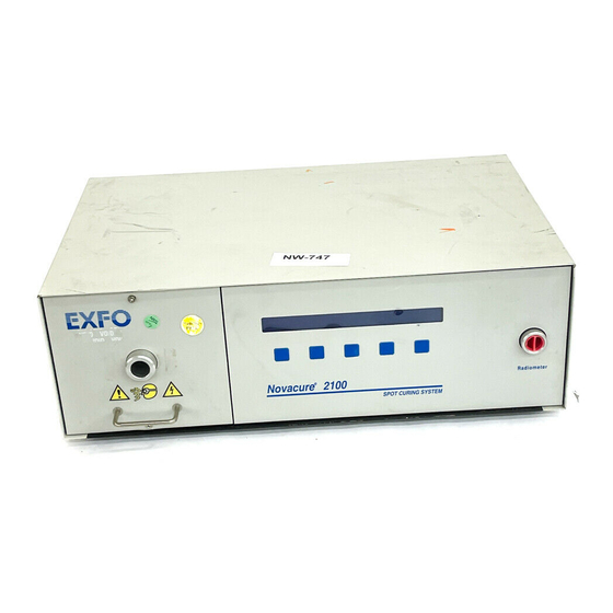
Front panel Lamp Housing Front Panel LCD And Keypad Radiometer Port Rear Panel A Fan with Filter B AC Receptacle Module (main inlet) C Intensity Monitor Output/Shutter Interlock Input D D-Sub, 9 pin socket Connector (data download) E High density D-Sub, 15 pin male Connector (I/O signal port) Setting Up the Novacure Artisan Technology Group - Quality Instrumentation ... -
Page 19: Installing / Replacing The Lamp Module
3.4 Installing / Replacing the Lamp Module 1. Be sure the AC power cord is disconnected from the unit. 2. Remove the two hexcap screws with the supplied tool from the lamp housing front panel and set them aside. 3. Hold the lamp housing handle and give it a firm, controlled pull to disengage it from the internal electromechanical connections. - Page 20 Disconnect the positive and negative terminals from the lamp. Remove the lamp from the spring clips. *Contact the service department to return all lamps in their original packaging to EXFO Photonic Solutions Inc. for disposal A, C : Ceramic components.
- Page 21 A: Positive terminal. B: Negative terminal. C, G : Spring clips. D: Back edge of module bracket. E: Ceramic mount. F: Locating notch. H: Temperature sensor termination. 8. Locate the lamp module power wires and move them into a position so they do not interfere with the lamp module placement.
-
Page 22: Care And Handling Of Your Lamp Module
Care and handling of your lamp module The lamp module used in the Novacure is a precision optical device that is sensitive to misuse. More importantly, it is sensitive to extreme shock and vibration, heat, length of operation and run up times. -
Page 23: Bandpass Filter Replacement
Bandpass filter replacement 1. Open the lamp housing drawer by following steps 1 through 4 in section 3.4. 2. Remove the filter assembly retainer from its packaging. Ensure that the filter portion of the assembly does not come in contact with any objects. 3. -
Page 24: Inserting The Light Guide
Inserting the light guide 1. Insert the light guide into the light guide retainer until it seats with a positive click. 2. Never grip the light guide during installation or removal in a place other than the strain-relief nearest the I/P end of the light guide. Removing the light guide 1. - Page 25 Turning Power on to the Novacure Artisan Technology Group - Quality Instrumentation ... Guaranteed | (888) 88-SOURCE | www.artisantg.com...
-
Page 26: Turning Power On To The Novacure
Turning Power on to the Novacure Powering Up Powering Down Turning Power on to the Novacure Artisan Technology Group - Quality Instrumentation ... Guaranteed | (888) 88-SOURCE | www.artisantg.com... -
Page 27: Powering Up
Powering up Plug the unit into a properly grounded AC outlet. 2. Ensure the lamp drawer is fully engaged, a lamp and filter have been installed and that the cover is completely closed. 3. Turn on the power switch and check the fan at the rear for air flow. Your LCD and fan should now be active. -
Page 28: Powering Down
Powering down The Novacure’s automatic cool down cycle enables the user to turn the mains switch to the off position, allow it to cool down the lamp module on its own, then shut itself off once the lamp module has reached the proper temperature. To power down the Novacure, simply switch the mains power switch to the OFF position. - Page 29 Turning Power on to the Novacure Artisan Technology Group - Quality Instrumentation ... Guaranteed | (888) 88-SOURCE | www.artisantg.com...
-
Page 30: Programming The Novacure
Programming the Novacure 5.1 Viewing/selecting a register 5.2 Running a register 5.3 Working from the set up menu 5.4 Setting the clock/calendar 5.5 Setting up registers (application parameters) 5.5.1 Set up #1: Intensity 5.5.2 Set up #2: Exposure Time 5.5.3 Set up #3: Dose 5.5.4 Set up #4: Dwell Interval... -
Page 31: Viewing/Selecting A Register
Viewing/selecting a register Register A set of user defined and programmed parameters that automate the curing procedure. Definable parameters include intensity, dose, operation mode, exposure time and dwell time. The Novacure allows users to define up to four registers. These registers are initially factory programmed to common settings that you can modify immediately. -
Page 32: Running A Register
Running a register Run The execution of a Novacure register. 1. Select Run: from the main menu. There are a number of menus that give you the MMenu: (main menu) prompt. If your current menu does not show the prompt, continue through its commands until it appears. -
Page 33: Working From The Set Up Menu
Working from the Set Up menu 1. Select Set Up: from the main menu. There are a number of menus that give you the MMenu: (main menu) prompt. If your current menu does not show the prompt, continue through its commands until it appears. Then press MMenu:. 2. -
Page 34: Setting The Clock/Calendar
Setting the clock/calendar 1. Move to the second set up menu. (See section 5.3) 2. Press ClkCal:. Set Up..(2) ClkCal: LtGd: StepCure: More: Back: 3. Use the first four keys (+Year; +Month; +10Day; and +1Day) to set the numbers corresponding to the current date. Now press OK:. Date (YY/MM/DD): YY/MM/DD +Year... -
Page 35: Setting Up Registers (Application Parameters)
Setting up registers (application parameters) 1. Move to the first set up menu. (See section 5.3) 2. Press Exposure:. Set Up..(1) M-Op: Exposure: Passwrd: More: MMenu: 3. Press No:. Current register=X...Select Another Reg? Yes: If you press Yes: another register can be viewed and selected. (See section 5.1) What you can do from here Setup Parameters for Register X.. -
Page 36: Setup #1: Intensity
5.5.1 Setup #1: Intensity Intensity The procedure that first measures and displays the maximum lamp module intensity available, measured in mW/cm , then allows you to set a desired intensity level and exposure time. Prior to setting up the intensity ensure that the light guide diameter setting matches that of the light guide being used (see section 5.9). - Page 37 5. Use the first three keys (+10Secs; +1Sec; and +.1Sec)to set up the desired exposure time in seconds. Now press Min:. Time= XX Mins / XX>X Secs +10Secs: +1Sec: +.1Secs: Min: This menu enables you to set a time up When you press Min: you toggle back to a maximum of 59 minutes, 59.9 to the minutes’...
- Page 38 What you can do from the Test/Run menu I=XXXXX/XXXXXmW D=XXXXXmJ L=XXXXHr R=X T=XX:XX.X Dw=NNN Cont: Run: Abort: • Press Cont: to move to the menu below • Press Run to initiate a test cycle exposure. (Note that the dwell function is inoperative during this test cycle.
-
Page 39: Setup #2: Exposure Time
5.5.2 Setup #2: Exposure Time Features to note The exposure time parameter is a mandatory input during both the intensity and dose set up. If the exposure times entered during the intensity and/or dose set up are acceptable, they do not need to be reentered here. The purpose of the exposure time menu selection is to provide the operator with an efficient way of changing exposure times only. - Page 40 What you can do from the Test/Run menu I=XXXXX/XXXXXmW D=XXXXXmJ L=XXXXHr R=X T=XX:XX.X Dw=NNN Cont: Run: Abort: • Press Cont: to move to the menu below • Press Run to initiate a test cycle exposure. (Note that the dwell function is inoperative during this test cycle.
-
Page 41: Setup #3: Dose
5.5.3 Setup #3: Dose Features to note When you set a dose value, the Novacure automatically calculates and sets intensity and exposure time values that enable it to efficiently produce the desired dose. If you modify either the register’s desired intensity or if the lamp module’s maximum available intensity decreases, the Novacure automatically increases the exposure time to enable it to produce the desired dose. - Page 42 5. Use the first three keys (+10000; +1000; +100; and 10) to set up the desired dose in Joules/cm2. Now press mJoules,then press OK:. When you press mJoules: you toggle to the mJoules’ parameters menu. You can then toggle back to the Joules’ parameters menu by pressing mJoules: until you have precisely defined your dose.
- Page 43 What you can do from the Test/Run menu I=XXXXX/XXXXXmW D=XXXXXmJ L=XXXXHr R=X T=XX:XX.X Dw=NNN Cont: Run: Abort: • Press Cont: to move to the menu below • Press Run to initiate a test cycle exposure. (Note that the dwell function is inoperative during this test cycle.
-
Page 44: Setup #4: Dwell Interval
5.5.4 Setup #4: Dwell Interval Dwell A user defined time value that enables the Novacure to produce repeated exposures with a defined time interval between exposure cycles. See also section 5.8, StepCure. Press Dwell:. Setup Parameters for Register X..Intensity: Time: Dose: Dwell: MMenu:... -
Page 45: Choosing Mode Of Operation
Choosing mode of operation Mode Of Operation Allows the user to select the source of the exposure trigger. (See section 9.3 for I/O signal descriptions.) Keypad (keypad:) Run a complete cure cycle when the Run: keypad is pressed External Control Mode Run a complete cure cycle with a single trigger from an external source (footpedal, I/O). -
Page 46: Choosing A Password
Choosing a password Password A user defined four digit number composed of any combination of the numbers 1,2,3, and 4 that must be entered to modify any setup settings. The factory programmed default password is 1111. This makes it quicker and easier to access the setup menus. However it does also make it easier for unauthorized people to modify these parameters. -
Page 47: Setting Up Stepcure
Setting up StepCure ® StepCure . Allows the user to program in an exposure during which the exposure time, intensity and dwell times are independently varied as per the pre-programmed register settings. A StepCure cycle will deliver timed exposures as per the settings contained in each of the registers, ®... -
Page 48: Selecting The Correct Light Guide Diameter
Selecting the correct light guide diameter Light Guide Diameter Selection. Allows the user to select one of 10 standard light guide diameters so that the Novacure can properly calculate the irradiance settings associated with the user’s light guide and application. 1. -
Page 49: Turning The History Data Saving On/Off
5.10 Turning the History data saving On/Off History data savings: The Novacure unit has the ability to monitor its functionality with system reporting. The Novacure reports internal calibrations, accumulated hours on the bulb, intensity requested and the number of exposures, by date and time. The data is saved in the unit memory, where it can then be downloaded to a PC. -
Page 50: Turn Extended Life Feature On/Off
5.11 Turn Extended Life feature On/Off Extended Life: The Novacure has the ability to decrease the power to the lamp, resulting in extended lamp life. The initial max. intensity available from the lamp will be lower if the extended life feature is activated. 1. - Page 51 Programming the Novacure Artisan Technology Group - Quality Instrumentation ... Guaranteed | (888) 88-SOURCE | www.artisantg.com...
-
Page 52: Using The Radiometer
Using the Radiometer Using the Radiometer Artisan Technology Group - Quality Instrumentation ... Guaranteed | (888) 88-SOURCE | www.artisantg.com... - Page 53 250 – 600nm bandwidth for unmatched functionality. The proprietary optical interface virtually eliminates beam profile dependence. The radiometer calibration is traceable to NIST, and it is recommended that the radiometer be returned to EXFO Photonic Solutions for calibration every six months.
- Page 54 4. Press Cont:. 5. Follow the displayed instructions. Insert light guide into receptacle on front panel for intensity reading...OK: This message is displayed if the Max or Current mode has been selected. 6. Press OK:. Intensity=XXXXX mW/cm2 Light Source=Current Cont: This displays the regulated light intensity reading of your light source in real time.
- Page 55 Using the Radiometer Artisan Technology Group - Quality Instrumentation ... Guaranteed | (888) 88-SOURCE | www.artisantg.com...
-
Page 56: Calibrating The Novacure
Calibrating the Novacure Calibrating the Novacure Artisan Technology Group - Quality Instrumentation ... Guaranteed | (888) 88-SOURCE | www.artisantg.com... - Page 57 You will hear a click. This is the sound of the on/off shutter opening that begins the automatic calibration sequence. If required the calibration routine can be bypassed by pressing the SKIP button. EXFO Photonic Solutions Inc. does not recommend this procedure as system accuracy will be compromised.
-
Page 58: Data Downloading
Data Downloading 8.1 Hardware Requirements 8.2 Installing Opto Link 2100 8.3 When you should download data 8.4 Performing a history download 8.5 Clearing the history data from the unit 8.6 Turning On/Off saving the history data 8.7 Typical history data download Data Downloading Artisan Technology Group - Quality Instrumentation ... -
Page 59: Hardware Requirements
Hardware Requirements The following hardware is required for using the History download feature: • A PC or notebook computer with an available 9-pin RS-232 serial port • A 9-pin male to 9-pin female, one-to-one serial cable 8.1.1 Opto Link 2100 min. Computer Configuration •... -
Page 60: Creating A Shortcut To Opto Link 2100
8.2.1 Creating a Shortcut to Opto Link 2100 1. From the Windows desktop double-click My Computer. 2. Double-click the C: drive. 3. Double-click the Novacure directory name where Opto Link 2100 is located 4. Right click the Opto Link 2100.exe file. 5. -
Page 61: When You Should Download Data
When you should download data Data downloading must be done when the "Memory almost full. Do a history download or data will be lost” message appears, or once for each 1000 hours operating time. If you ignore the error message, the Novacure continues writing new performance history data over the previous history data. -
Page 62: Clearing The History Data From The Unit
8.5 Clearing the History data from the Unit If you would like to clear the history data from the Novacure unit’s memory, without saving the data: 1. Follow steps 1 to 3 from section 8.4 Performing a History download 2. Under data logging, click on Clear History. A warning message will appear that you are about to clear the history data 3. -
Page 63: Typical History Data Download
Typical history data download Data Downloading Artisan Technology Group - Quality Instrumentation ... Guaranteed | (888) 88-SOURCE | www.artisantg.com... -
Page 64: Interfacing With The Novacure
9 Interfacing with the Novacure 9.1 Connection options 9.2 Input and output signals 9.3 Signal descriptions Interfacing with the Novacure Artisan Technology Group - Quality Instrumentation ... Guaranteed | (888) 88-SOURCE | www.artisantg.com... -
Page 65: Connection Options
Connection options The data downloading connector (RS-232), a D-Sub 9-position socket can be accessed via a standard 9 pin (one to one) serial cable. The other end can be connected to any free serial port on the PC or laptop, which is to be used for interfacing. (see Section 8). All of the input and output signals are available on the (High-Density) HD D-Sub 15 pin male connector. -
Page 66: Input And Output Signals
Shutter Interlock input (positive) Shutter Interlock input (common) A shielded cable is required for use with this port. Note: The mating 4 position connector can be purchased from EXFO Photonic Solutions Inc. (p/n 020- 00474). Interfacing with the Novacure Artisan Technology Group - Quality Instrumentation ... Guaranteed | (888) 88-SOURCE | www.artisantg.com... - Page 67 The I/O signal connector, the HD D-Sub 15 pin male, has the following pin-out: PIN NO. SIGNAL NAME NOTES Common (GND) Return for input signals Trigger Input Momentary contact, active low Client Status Output, positive Collector of NPN transistor, output side of optocoupler Client Status Output, common Emitter of NPN transistor, output...
- Page 68 The specifications for the input and output signals are as follows: Output Signals: >polarized type: NPN transistor (output side of optocoupler) >maximum voltage withstand 30VDC capability (V >maximum carry current: 10mA The output signals are accessible on the transistor output of each optocoupler. By providing access to both the collector (+) and the emitter (-) separately for each signal, the user can use each output as an active high or active low signal thereby increasing the flexibility of the Novacure.
-
Page 69: Signal Descriptions
Signal descriptions 9.3.1 D-Sub 9-position socket connector Connector D-Sub 9-position socket, pins 1 through 9: RS232 interface. (Note: Only pins 1 thru 4 are actually utilized) This connector is to be connected to any free serial port of the (laptop) computer, which is to be used for downloading the history information contained within the Novacure. - Page 70 Connector HD D-Sub 15 pin male, pin 8: calibrate input This input signal can be used to initiate a calibration procedure remotely without the need to use the front panel controls. (See also Section 7 for additional information). This input is a zero voltage type of input.
-
Page 71: Position Circular Connector
Connector HD D-Sub 15 pin male, pin 13: remote power ON/OFF input This signal can be used to initiate the power down sequence during which the lamp is shut off, allowed to cool down, then AC power is automatically switched OFF for the entire unit. This input is a zero voltage type of input. -
Page 72: Error Messages
Error Messages Error Messages Artisan Technology Group - Quality Instrumentation ... Guaranteed | (888) 88-SOURCE | www.artisantg.com... - Page 73 The Novacure is designed to advise/warn you when it detects a procedural or operational problem. The following messages appear on the LCD when the appropriate conditions are met. In some cases, as indicated below, an alarm sounds and a message appears on the LCD. These messages serve to warn you of an operational problem and will stop any active exposures.
- Page 74 Output intensity is too low. Check the light guide. Cont: Possible Causes Solution Light guide has poor transmission Replace the light guide with qualities due to age or physical a new one damage Light guide has adhesive or other Clean the light guide matter cured onto it's emitting end emitting end with an appropriate cleaning...
- Page 75 Install a new lamp drawer as The proportional shutter is stuck per section 11.6 or return the in the closed position unit to EXFO Photonic Solutions Inc. as per section 15.2 The lamp module was installed See section 3.4 for correct installation procedure.
- Page 76 System Fault! Shutter opened prematurely Possible Causes Solution The light guide was installed See section 3.7 and 12.1 incorrectly and 12.4. The shutter movement is sluggish See section 15.2 or the shutter is stuck open The light guide detection See section 15.2 microswitch requires calibration / service Too soon for lamp out.
- Page 77 Too soon to strike arc. Waiting: NNN% Waiting for lamp to cool. Possible Causes Solution The lamp is too hot (perhaps the Let the Novacure control the cool down mode was bypassed lamp cool down and increase during an earlier shut-down) the interval between shutting down and powering up the Novacure...
-
Page 78: Maintenance And Service
Warning: Routine Maintenance and Service is to be performed only by Qualified Service Personnel. Maintenance and Service 11.1 Routine care and maintenance 11.2 Replacing the external fuse 11.3 Removing the cover 11.4 Re-Attaching the cover 11.5 Replacing the radiometer 11.6 Replacing the lamp housing drawer Maintenance and Service Artisan Technology Group - Quality Instrumentation ... -
Page 79: Routine Care And Maintenance
11.1 Routine care and maintenance 1. Operate the unit in a well ventilated area with at least six inches clearance at the rear of the unit for proper air flow. 2. For safe operation, use only a grounded outlet. 3. Avoid physical shocks or jarring to the unit especially while the unit is operating. Such sudden movements reduce the lamp module life. -
Page 80: Replacing The External Fuses
11.2 Replacing the external fuses The external (main) fuses are located in the fuse drawer located in the AC inlet module on the rear panel. 1. Turn off the main power switch and remove the AC power cord from the unit. 2. -
Page 81: Removing The Cover
11.3 Removing the cover Service to be completed by qualified repair personnel only! Caution High voltages are present within the unit. Remove the AC power cord from the unit prior to removing the cover. 1. Turn the mains power switch off. 2. -
Page 82: Replacing The Radiometer
11.5 Replacing the radiometer Service to be completed by qualified repair personnel only! 1. Remove the unit cover. (See section 11.3) Locate the radiometer and carefully disconnect the 4 conductor I/O cable from the radiometer. 3. Remove the two #6 Philips screws as shown. 4. -
Page 83: Replacing The Lamp Housing Drawer
11.6 Replacing the lamp housing drawer Service to be completed by qualified repair personnel only! Bottom mounted stop screws 1. Turn the mains power switch off. 2. Remove the AC power cord. 3. Carefully turn the unit upside down. 4. Unscrew the two end stop screws from the bottom of the unit. Place the screws aside for later use. - Page 84 12. If the lamp module in the old lamp drawer is known to function properly it can be installed into the new lamp drawer. If the lamp module is of questionable quality, a new lamp module should be installed. Refer to Section 3.4. 13.
- Page 85 Maintenance and Service Artisan Technology Group - Quality Instrumentation ... Guaranteed | (888) 88-SOURCE | www.artisantg.com...
-
Page 86: Troubleshooting
Warning: Routine Maintenance and Service is to be performed only by Qualified Service Personnel. Troubleshooting 12.1 Check these areas first 12.2 Unit does not power up 12.3 Lamp module does not power up 12.4 Shutter does not open 12.5 Light intensity is too low 12.6 Maximum intensity available during exposure set up is abnormally high or low 12.7 Radiometer check produces abnormally low or high intensity reading 12.8 Fan does not work properly... -
Page 87: Check These Areas First
12.1 Check these areas first In the event that a unit does not perform properly or fails, try going through this troubleshooting checklist step by step to help locate and eliminate problems. This checklist is not intended to serve as repair instructions. Service to be completed by qualified repair personnel only! Check that: 1. -
Page 88: Unit Does Not Power Up (Fan, Display Not Functional)
12.2 Unit does not power up (fan, display not functional) 1. Ensure that the cover is in place and that all securement hardware is in place. 2. Ensure that the lamp drawer is seated properly within the Novacure and that the securement hardware is in place. -
Page 89: Shutter Does Not Open
12.4 Shutter does not open 1. Ensure that with the AC power switch in the ON position, the fan is functional and the LCD is on. If the fan and the LCD are not functional refer to 12.2. 2. Verify that the lamp module has been turned on successfully. An error message appears if the lamp module fails to turn on. -
Page 90: Light Intensity Is Too Low
12.5 Light intensity is too low Danger Never look into the emitting end of the light guide. 1. Ensure that the shutter is opening and that some discernible amount of light energy is being emitted from the light guide. If the emitting end of the light guide is not transmitting any amount of light energy, and the shutter is not opening, refer to section 12.4. -
Page 91: Radiometer Check Abnormally Low /High
12.7 Radiometer check abnormally low /high 1. During the radiometer check ensure that the emitting end of the light guide is fully inserted into the radiometer port and that the correct adapter is being used. 2. With the unit powered up and from the main menu, press the Radiomtr: key. Depress the Max: key and insert the emitting end of the light guide fully into the radiometer port. -
Page 92: Fan Speed Is Too Slow After Warm Up
12.9 Fan speed is too slow after warm up 1. If after a five minute warm up period the fan speed is still too slow, open the lamp drawer as per instructions in section 11.6. Ensure that the lamp module temperature sensor is plugged into its mating receptacle. -
Page 93: Data Downloading Doesn't Work Properly
12.13 Data downloading doesn't work properly 1. Ensure that the serial cable is connected properly to the Novacure as well as to the PC. Ensure the serial cable is a "one to one" type (pin 1 connected to pin 1, pin 2 to pin 2 etc.). 2. -
Page 94: Remote Input Signals Do Not Work
12.15 Remote input signals do not work 1. Ensure that the correct connections have been made to the (High-Density) HD D-Sub 15 pin male connector. See section 9. 2. Ensure that the correct power supply polarity and voltage levels have been used to power the I/O signals via the (High-Density) HD-Sub 15 pin male connector. -
Page 95: Toll Free Customer Service
12.18 Toll free customer service In Canada & the USA TOLL FREE, 1-800-668-8752 OR 1-905-821-2600 Troubleshooting Artisan Technology Group - Quality Instrumentation ... Guaranteed | (888) 88-SOURCE | www.artisantg.com... -
Page 96: Technical Specifications
Technical Specifications 13.1 Lamp module 13.2 Light guide 13.3 Removable radiometer 13.4 Power supply and battery backup 13.5 Environmental Conditions 13.6 Regulatory Compliance 13.7 Mechanical Specifications 13.8 Miscellaneous Technical Specifications Artisan Technology Group - Quality Instrumentation ... Guaranteed | (888) 88-SOURCE | www.artisantg.com... -
Page 97: Lamp Module
13.1 Lamp module A, D: Ceramic Components. B: Reflector Cup. C: Bulb. E: Temperature Sensor Termination Lamp Module High Pressure 100 Watt Mercury Vapor Short Arc Lamp Module Life 2000 hours continuous running in long life mode (typical),1000 hours in standard mode (typical) UV/Visible Output User adjustable and maintained Warm Up... -
Page 98: Light Guide
13.2 Light guide Light Delivery Flexible liquid filled light guide .75 to 3 metres in length with core diameters of 3mm, 5mm and 8mm. Dual and triple light guides available with 3mm core diameter. Custom light guides, quartz fiber light guides and specialty optics also available. Liquid Light Guide End Fitting Liquid Light Guide Dimensions in mm Core... -
Page 99: Removable Radiometer
13.3 Removable radiometer Intensity Range 0-99,000 mW/cm Spectral Range 250-600 nanometers (nm) Resolution 20 mW/cm Accuracy +/-5% typical, 10% maximum Display Novacure LCD Calibration Traceable to NIST, recommended every 6 months Adapters To suit 3mm and 5mm light guides. An 8mm light guide can be accommodated without an adapter Technical Specifications... -
Page 100: Power Supply And Battery Backup
13.4 Power supply and battery backup Power Supply Proprietary, High efficiency, switch mode, constant power output Input Voltage 100-120VAC and 200-240VAC, 50/60 Hz, auto-range selection Current 3A Max Inrush Current Inrush current protection less than 50A at 90°, ½ line cycle, cold start Protection Dual fuse system: each fuse rated at F4A 250V (Fast acting type) EMI filtering integrated into the power supply... -
Page 101: Environmental Conditions
13.5 Environmental Conditions Operating Environment Conditions Installation Category II, Pollution Degree 2 Temperature: 10 to 40 degrees Celsius Relative Humidity: 30% to 75% (non-condensing) Atmospheric Pressure: 700 to 1060 hPa Altitude: 2,000 meters (maximum) Transport and Storage Conditions Temperature: -20 to 70 degrees Celsius Relative Humidity: 10% to 100% (non-condensing) Atmospheric Pressure: 500 to 1060 hPa 13.6... -
Page 102: Mechanical Specifications
WARNING Changes or Modifications not expressly approved by EXFO PHOTONIC SOLUTIONS INC.Inc. could void the user's authority to operate the equipment. NOTE: All cable assemblies used with the NOVACURE MUST BE SHIELDED! Use only the shielded power supply cord and the footswitch cable assembly supplied with the Novacure. - Page 103 Technical Specifications Artisan Technology Group - Quality Instrumentation ... Guaranteed | (888) 88-SOURCE | www.artisantg.com...
-
Page 104: Replacement Parts
Replacement Parts 14.1 Ordering information 14.2 Standard parts and accessories 14.3 Optional light guides 14.4 Specialty Optics Replacement Parts Artisan Technology Group - Quality Instrumentation ... Guaranteed | (888) 88-SOURCE | www.artisantg.com... -
Page 105: Ordering Information
(418) 683-0211 Fax: (418) 681-3936 Toll Free: 1-800-663-3936 e-mail: bdg.toronto@exfo.com www: exfo-uv.com For International and Canada EXFO ELECTRO-OPTICAL ENGINEERING Inc. 400 Godin Avenue Vanier, Quebec G1M 2K2 Canada Tel: (418) 683-0211 Fax: (418) 681-3936 Toll Free: 1-800-663-3936 (USA and Canada) e-mail: bdg.toronto@exfo.com... -
Page 106: Standard Parts And Accessories
Light guide locking ring *Contact the sales or service department to return all lamps in their original packaging to EXFO Photonic Solutions Inc. for disposal Replacement Parts Artisan Technology Group - Quality Instrumentation ... Guaranteed | (888) 88-SOURCE | www.artisantg.com... -
Page 107: Optional Liquid Light Guides
14.3 Optional liquid light guides Part No. Description 805-00005 Liquid, 3mm x 750mm 805-00004 Liquid, 3mm x 1000mm 805-00022 Liquid, 3mm x 1500mm 805-00006 Liquid, 5mm x 750mm 805-00002 Liquid, 5mm x 1000mm 805-00007 Liquid, 5mm x 1500mm 805-00008 Liquid, 5mm x 3000mm 805-00009 Liquid, 8mm x 1000mm 805-00010... -
Page 108: Specialty Optics
14.4 Specialty optics Specialty optics can be purchased from EXFO Photonic Solutions Inc. to optimize the delivery of light from the Novacure to the sample. Using these optics, both the spatial and spectral properties of the Novacure output can be customized. - Page 109 019-01007 Filter assembly, 250-450nm 019-01006 Filter assembly, 365nm 019-01008 Filter assembly, 400-500nm* * Contact your EXFO representative for information about using the 400-500nm filter in the Novacure 2100 810-00001 angle for 3mm light guide 810-00002 angle for 5mm light guide...
-
Page 110: Warranty
Warranty 15.1 Novacure warranty 15.2 Returning your Novacure to EXFO 15.3 EXFO Service Centers Warranty Artisan Technology Group - Quality Instrumentation ... Guaranteed | (888) 88-SOURCE | www.artisantg.com... -
Page 111: Novacure Warranty
15.1 Novacure Warranty EXFO warrants the original purchaser for a period of one (1) full year, calculated from the date of purchase, that the equipment sold is free from defects in material and workmanship. In the event of a claim under this guarantee, the equipment is to be sent postage and carriage paid, including a description of the fault, to the EXFO Service Center. -
Page 112: Returning Your Novacure To Exfo
3. Enclose details of the problem with the unit and return both to the EXFO Service Center. The unit should be returned in its original packaging if possible. Please do not ship the unit with the lamp installed. -
Page 113: Exfo Service Centers
15.3 EXFO Service Centers Service information may be obtained by contacting your nearest EXFO Service Centre: EXFO Photonic Solutions Inc. 1-800-668-8752 (USA and Canada) 2260 Argentia Rd. Tel: (905) 821-2600 Mississauga, Ontario L5N 6H7 Fax: (905) 821-2055 CANADA UVSupport@exfo.com www.exfo-uv.com... - Page 114 Warranty Artisan Technology Group - Quality Instrumentation ... Guaranteed | (888) 88-SOURCE | www.artisantg.com...
- Page 115 Artisan Technology Group - Quality Instrumentation ... Guaranteed | (888) 88-SOURCE | www.artisantg.com...
- Page 116 Artisan Technology Group - Quality Instrumentation ... Guaranteed | (888) 88-SOURCE | www.artisantg.com...
- Page 117 Printed in Canada 035-00186 Rev. 3 Artisan Technology Group - Quality Instrumentation ... Guaranteed | (888) 88-SOURCE | www.artisantg.com...
Need help?
Do you have a question about the Novacure 2100 and is the answer not in the manual?
Questions and answers