Table of Contents
Advertisement
Quick Links
Advertisement
Chapters
Table of Contents

Related Manuals for EXFO XTM-50 Series


Summary of Contents for EXFO XTM-50 Series
- Page 1 XTA-50 Optical Tunable Filter User Guide www.EXFO.com XTA-50_UG_2.1v2.3...
-
Page 3: About This Manual
About This Manual Subject This manual explains how to install operate the XTA-50 optical tunable filter in local and remote modes. It also explains how to perform basic maintenance operations. Application Information in this document applies to the firmware version 2.1.x. Intended Readers Users of this manual must be familiar with: •... - Page 4 (electronic, mechanical, magnetic, optical, chemical, photocopying, manual, or otherwise) without the prior written permission of EXFO. Product Warranty For detailed information about the sales terms and conditions, visit the EXFO web site at and Limitation of www.exfo.com/how-to-buy/sales-terms-conditions Warranty...
-
Page 5: Table Of Contents
Table of Contents About This Manual ............................. 3 Table of Contents ............................5 Safety Information ............................. 7 Product Presentation .......................... 9 Technical Specifications ........................9 Product Overview ..........................11 1.2.1 Front Panel Description ......................12 1.2.2 Rear Panel Description ......................13 Installing and Connecting the XTA-50 .................... - Page 6 Table of Contents Remotely Controlling the XTA-50 via RS-232 ..................41 5.5.1 Setting the XTA-50 RS-232C Port ..................41 5.5.2 Controlling the XTA-50 via RS-232..................41 Controlling the XTA-50 Graphical Interface from an External Screen ..........43 Remotely Controlling the XTA-50 via IEEE-488 with an External Controller........44 5.7.1 Setting the GPIB Address ......................
-
Page 7: Safety Information
Keep this information close at hand. You can obtain a copy of the complete user guide for your product at the following link: www.EXFO.com Important • If you see the symbol on your unit, make sure that you refer to the instructions provided in this safety notice. - Page 8 If the equipment is used in a manner not specified by the manufacturer, the protection provided by the equipment may be impaired. • Use only accessories designed for your unit and approved by EXFO. For a complete list of accessories available for your unit, see its technical specifications or contact EXFO.
-
Page 9: Product Presentation
1. Product Presentation The XTA-50 is a flat-top tunable filter for fiber-optic component and system testing. It is designed for closely-spaced channel selection and extraction in DWDM applications. When an optical signal is detected at the XTA-50 input port, the input wave is directed towards the output port after passing through the XTA-50 monochromator, which is tuned at the center wavelength via the XTA-50 software. - Page 10 Product Presentation *4: Between -3 and -40 dB. Typically 550 dB/nm @ FWHM = 50 pm, 450 dB/nm @ FWHM= 1 nm, 225 dB/nm @ FWHM = 5 nm. *5: From 1500 to 1600 nm & FWHM >100 pm. *6: At lowest FWHM the insertion loss is 7 dB typical. *7: From 1500 to 1600 nm &...
-
Page 11: Product Overview
Product Presentation Environmental & Physical Standard Ultrafine O-band Wide Specifications Environmental Specifications Equipment Type Test and Measurement Equipment Location Indoor use only Basic insulation, as defined in IEC-61010-1. Safety Class Grounded product. Category II Local-level mains (wall sockets). Equipment at this level Overvoltage Category includes appliances, portable tools, and similar products. -
Page 12: Front Panel Description
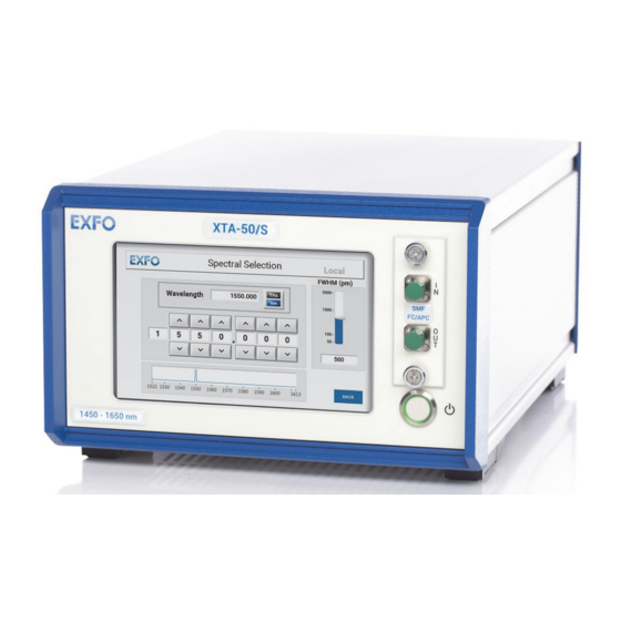
Product Presentation 1.2.1 Front Panel Description Touch Screen Optical Connectors Connector’s drawer On/Off Switch Retractable Leg Figure 1: Front Panel Touch Screen The touch screen enables you to perform all possible operations on the XTA-50. To select a parameter, command or function on the screen, touch the corresponding command with the tip of your finger or a touch screen stylus device. -
Page 13: Rear Panel Description
DC connector. Caution To ensure the smooth functioning of the XTA-50, you must only use the power adapter provided by EXFO. Fuse Holder The fuse holder contains a fuse (see section Technical Specifications, p. 9 for fuse type) to protect the XTA-50 from overcurrent. - Page 14 Product Presentation • Ethernet RJ45 ports enables you to connect a computer/network for Ethernet remote control. • Ethernet port LAN1: This port is associated with a DHCP server. It can be used to connect directly a computer that will be assigned automatically an IP address. •...
-
Page 15: Installing And Connecting The Xta-50
When unpacking, handle the device with care and do not damage the original shipping container in case the XTA-50 needs to be returned to EXFO. 2. Pull out the XTA-50 vertically from its packaging. 3. Set the XTA-50 on a flat stable surface free of excessive vibration and make sure you can easily reach the rear of the instrument to remove the power supply cord if necessary. -
Page 16: Connecting The Xta-50 To A Power Source
• The XTA-50 system is intended to operate from an external power adapter 12V/8A. Use the one provided by EXFO at instrument delivery or contact EXFO for replacement unit. Procedure 1. Make sure the power adapter is not plugged to the wall socket. -
Page 17: Connecting An Optical Source To The Xta-50
Installing and Connecting the XTA-50 Connecting an Optical Source to the XTA-50 Subject Caution • Make sure you use the appropriate connector type, corresponding to the one mounted on your XTA-50 (see section Technical Specifications, p. 9 for available models). •... - Page 18 Installing and Connecting the XTA-50 XTA-50 User Guide...
-
Page 19: Turning On/Off The Xta-50
3. Turning on/off the XTA-50 Turning On the XTA-50 and Accessing the Operating Modes Subject The Operating Mode window enables you to access all XTA-50 functions. Before Starting Make sure the XTA-50 is properly installed: see section Installing and Connecting the XTA-50, p. -
Page 20: Checking The Firmware Version
Turning on/off the XTA-50 Button Description Corresponding Section Enables you to manually set the section Manually Entering the wavelength/frequency and Wavelength/Frequency and FWHM FWHM values. Values, p. 23 Enables you to select and use an section Using a Predefined Grid to ITU grid to rapidly select a Select a Channel, p. -
Page 21: Setting The Screen Brightness
Turning on/off the XTA-50 Setting the Screen Brightness Subject You can control the screen brightness from the Settings window, as explained in the following procedure. If you have connected an external screen to the XTA-50 (see section Controlling the XTA- 50 Graphical Interface from an External Screen, p. - Page 22 Turning on/off the XTA-50 XTA-50 User Guide...
-
Page 23: Setting The Wavelength/Frequency And Fwhm Values
4. Setting the Wavelength/Frequency and FWHM Values Manually Entering the Wavelength/Frequency and FWHM Values Subject The Spectral Selection function enables you to manually set the wavelength or frequency and FWHM values. Procedure 1. In the Operating Mode window, touch the Spectral Selection button. The Spectral Selection window appears. -
Page 24: Selecting A Channel By Using An Itu Grid
Setting the Wavelength/Frequency and FWHM Values a. In the FWHM area, touch the gauge. The virtual keypad appearing on screen is initialized with the value corresponding to the point you have touched on the gauge. b. Enter the wanted FWHM value using the virtual keypad. The available FWHM values are detailed in section Technical Specifications, p. -
Page 25: Figure 9: Itu Grid Selection Window
Setting the Wavelength/Frequency and FWHM Values Figure 9: ITU Grid Selection Window 2. Set the predefined grid you want to use: • Band: touch the button corresponding to the band you want to use. • Frequency Spacing: touch the button corresponding to the wanted spacing between two channels of the grid. -
Page 26: Using A Custom Grid To Select A Channel
Setting the Wavelength/Frequency and FWHM Values The virtual keypad appearing on screen is initialized with the value corresponding to the point you have touched on the gauge. b. Enter the wanted FWHM value using the virtual keypad. The available FWHM values are detailed in section Technical Specifications, p. 9. 4.2.2 Using a Custom Grid to Select a Channel Subject... -
Page 27: Figure 12: Custom Grid Window
Setting the Wavelength/Frequency and FWHM Values Figure 12: Custom Grid Window 3. Specify the wanted spectral unit by touching the button. • In wavelength mode: • FWHM unit is pm (picometer). • Wavelength unit is nm (nanometer). • In frequency mode: •... -
Page 28: Defining And Running A Sequence Of Wavelength/Frequency And Fwhm Values
Setting the Wavelength/Frequency and FWHM Values Defining and Running a Sequence of Wavelength/ Frequency and FWHM Values The Sequence Editor function enables you to create a list of wavelength and FWHM values that the XTA-50 will be able to execute without supervision. An instruction is composed of: •... -
Page 29: Running A Sequence
Setting the Wavelength/Frequency and FWHM Values • Wavelength/Frequency • FWHM • Delay: period of time between instruction execution (in seconds). Possible value: 0.1 to 100 seconds. 4.3.2 Running a Sequence Subject The XTA-50 provides two ways to execute a sequence: •... -
Page 30: Saving A Sequence
Setting the Wavelength/Frequency and FWHM Values Executing the Sequence Continuously 1. In the Sequence Editor window, touch the button. The Running Loop Sequence window appears and the sequence is automatically started. Figure 15: Sequence - Loop 2. To stop the sequence execution touch the button. -
Page 31: Loading A Sequence
Setting the Wavelength/Frequency and FWHM Values 4.3.4 Loading a Sequence Subject You can load a previously saved sequence, as explained in the following procedure. You cannot load a sequence from an external device. Procedure 1. In the Sequence Editor window, touch the button. -
Page 32: Enabling/Disabling The Backlash Suppression Mechanism
Setting the Wavelength/Frequency and FWHM Values Enabling/Disabling the Backlash Suppression Mechanism Subject When you change the wavelength/frequency or FWHM value, the XTA-50 automatically operates the backlash suppression mechanism to eliminate the effect of mechanical backlash on the tuning wavelength actuator: it moves 5 nm lower than the wanted wavelength/frequency before going to the requested wavelength/frequency. -
Page 33: Using The Xta-50 In Remote Mode
5. Using the XTA-50 in Remote Mode The XTA-50 features the following interfaces for remote control (see Figure 2, p. 13): • USB-B (see section Remotely Controlling the XTA-50 via USB-B, p. 35) • Ethernet (see section Remotely Controlling the XTA-50 via Ethernet, p. 38) •... -
Page 34: Installing/Updating And Starting The Xta-50 Remote Program
Procedure 1. From the XTA-50 USB key or the EXFO website, copy the Remote Client vx.xx folder to a local directory on your computer. 2. Double-click the setup.exe file located in the Remote Client vx.xx folder. -
Page 35: Remotely Controlling The Xta-50 Via Usb-B
USB-A • Make sure you have the appropriate XTA-50 USB driver. It is provided on the USB key delivered with the XTA-50, or you can download it from the EXFO website (www.exfo.com/software/exfo-apps). • If a previous version of the XTA-50 USB driver is already installed on your computer, uninstall it. -
Page 36: Controlling The Xta-50 Via Usb-B
Using the XTA-50 in Remote Mode 4. Connect the USB B port of the XTA-50 (see Figure 2, p. 13) to the USB-A port of your computer using a USB-B/USB-A cable. Important Do not connect your computer to the XTA-50 USB-A port. The USB remote mode is only available through the XTA-50 USB-B port. -
Page 37: Figure 18: Xta-50 Remote Client - Usb Communication
Using the XTA-50 in Remote Mode Controlling the XTA-50 Using the XTA-50 Remote Client If LabVIEW is not installed on your computer, do the following: 1. Install and start the XTA-50 Remote Client program on your computer as explained in section Installing/Updating and Starting the XTA-50 Remote Program, p. 34. If you don't intend to program with LabVIEW, you can use this software to check the connection between your computer and the XTA-50 via this interface. -
Page 38: Remotely Controlling The Xta-50 Via Ethernet
Using the XTA-50 in Remote Mode Remotely Controlling the XTA-50 via Ethernet The Ethernet port enables you to connect the XTA-50 to a computer or to a network to control it with remote commands. 5.4.1 Setting the XTA-50 Ethernet Ports Subject To connect the XTA-50 to a computer or network via the Ethernet port, use the Settings window to configure the IP address. -
Page 39: Controlling The Xta-50 Via Ethernet
Using the XTA-50 in Remote Mode Ethernet Ethernet Port 1 (Left) - DHCP server Parameter Displays the address automatically assigned to the XTA-50. Description Default XTA-50 IP address: 192.168.54.1 Ethernet Port 2 (Right) Specify the wanted IP configuration mode by touching the button. -
Page 40: Figure 20: Xta-50 Remote Client - Ethernet Communication
Using the XTA-50 in Remote Mode 2. Use the authorized remote commands detailed in section Available Remote Commands, p. 48 to remotely control the XTA-50. Controlling the XTA-50 Using the XTA-50 Remote Client If LabVIEW is not installed on your computer, do the following: 1. -
Page 41: Remotely Controlling The Xta-50 Via Rs-232
Using the XTA-50 in Remote Mode Remotely Controlling the XTA-50 via RS-232 The RS-232 port enables you to connect the XTA-50 to a computer to control it with remote commands. 5.5.1 Setting the XTA-50 RS-232C Port Subject If you want to use the RS-232 port of the XTA-50, use the Settings window to set the port, as explained in the following procedure. -
Page 42: Figure 22: Xta-50 Remote Client - Rs-232 Communication
Using the XTA-50 in Remote Mode • <XTA-50 USB key>\LabVIEW vx.xx\src\Ethernet USB GPIB RS232 clients.vi: this file contains a sample LabVIEW program for either an Ethernet, USB or GPIB RS232 interface. • <XTA-50 USB key>\LabVIEW vx.xx\src\RS232: this directory contains all the .vi files related to RS-232 control. -
Page 43: Controlling The Xta-50 Graphical Interface From An External Screen
Using the XTA-50 in Remote Mode Controlling the XTA-50 Graphical Interface from an External Screen Subject You can connect an external screen to the XTA-50 to display and control the graphical interface. Before Starting • Make sure you have a DVI cable to link the XTA-50 to your external screen. •... -
Page 44: Remotely Controlling The Xta-50 Via Ieee-488 With An External Controller
Using the XTA-50 in Remote Mode Remotely Controlling the XTA-50 via IEEE-488 with an External Controller Important Controlling the XTA-50 via GPIB is only available using an external NI RS-232/ GPIB converter. 5.7.1 Setting the GPIB Address Subject If you want to use the IEEE-488 interface (accessory) of the XTA-50, use the Settings window to configure the GPIB address. -
Page 45: Figure 24: Xta-50 Remote Client - Gpib Communication
Using the XTA-50 in Remote Mode • Link the COM2 port of the XTA-50 (see Figure 2, p. 13) to the RS-232 converter via the RS-232 cable delivered with the product and use a GPIB cable to link the GPIB converter to your application. -
Page 46: Figure 25: National Instrument - Max Configuration
Using the XTA-50 in Remote Mode Configuring the National Instrument Measurement & Automation Explorer (MAX) To directly send commands using the National Instrument Measurement & Automation Explorer (MAX), proceed to the configuration illustrated in Figure 25, p. 46: Figure 25: National Instrument - MAX Configuration XTA-50 User Guide... -
Page 47: Remote Control Commands
Using the XTA-50 in Remote Mode Remote Control Commands The XTA-50 specific commands and syntax are identical in USB, Ethernet, RS-232 and GPIB remote control modes. 5.8.1 Command/Answer Syntax Rules In remote mode the XTA-50 is a slave. It replies to the computer but will never instigate a communication. -
Page 48: Available Remote Commands
Using the XTA-50 in Remote Mode Command Error If the XTA-50 is not able to understand a command, it resends it (in uppercase and without space) preceded by the character "?": ?<Command><CR><LF> Error can come from a wrong parameter name, a wrong action identifier, a wrong value. For one command all operators are not always available. -
Page 49: General System Control
ETH_MANUAL?, p. 56 ETH_MANUAL? 5.8.2.1 General System Control *IDN? Syntax *IDN? Description Queries the XTA-50 identification string. Query Response EXFO,XTA-50,0,x.x.x where x.x.x is the firmware version. SERIAL_NUMBER? Syntax SERIAL_NUMBER? Description Queries the XTA-50 serial number. Query Response YOxxxxxxxxx XTA-50 User Guide... -
Page 50: Wavelength/Frequency And Fwhm Control
Using the XTA-50 in Remote Mode 5.8.2.2 Wavelength/Frequency and FWHM Control LAMBDA= Syntax LAMBDA=<value> Description Sets a new wavelength value in nm. If a sequence is running, the wavelength cannot be remotely assigned. In this case the XTA-50 answer is: SEQUENCE_RUNNING=TRUE •... - Page 51 Using the XTA-50 in Remote Mode FREQ= Syntax FREQ=<value> Description Sets the frequency value in THz. If a sequence is running, the wavelength cannot be remotely assigned. In this case the XTA-50 answer is: SEQUENCE_RUNNING=TRUE • <value>: string of a natural number, according to the frequency limits and the FWHM value.
- Page 52 Using the XTA-50 in Remote Mode FWHM? Syntax FWHM? Description Queries the current FWHM value in nm. Example FWHM? → 0.065 FWHM_F= Syntax FWHM_F=<value> Description Sets a new FWHM value in GHz. If a sequence is running, the FWHM cannot be remotely assigned. In this case the XTA- 50 answer is: SEQUENCE_RUNNING=TRUE •...
- Page 53 Using the XTA-50 in Remote Mode FWHM_MAX? Syntax FWHM_MAX? Description Queries the XTA-50 maximal FWHM value in nm. Query Response String of a natural number. SEQUENCE_ Syntax RUNNING? SEQUENCE_RUNNING? Description Queries if a sequence is currently running. In this case, the wavelength, frequency and FHWM cannot be remotely assigned.
-
Page 54: Remote Mode Control
Using the XTA-50 in Remote Mode 5.8.2.3 Remote Mode Control LOCAL Syntax LOCAL Description Ends remote mode, the XTA-50 comes back to local mode. ETH_IP= Syntax ETH_IP=<value>.<value>.<value>.<value> Description Sets a new IP address (for more details, see section Setting the XTA-50 Ethernet Ports, p. - Page 55 Using the XTA-50 in Remote Mode ETH_MASK? Syntax ETH_MASK? Description Queries the XTA-50 mask. Query Response String of four integers (0 to 255) separated by dots. Example ETH_MASK? → 255.255.255.0 ETH_GATEWAY= Syntax ETH_GATEWAY=<value>.<value>.<value>.<value> Description Sets a new gateway (for more details, see section Setting the XTA-50 Ethernet Ports, p.
- Page 56 Using the XTA-50 in Remote Mode ETH_AUTO? Syntax ETH_AUTO? Description Queries if the XTA-50 Ethernet parameters are currently in automatic mode. Query Response • TRUE: the XTA-50 Ethernet parameters are currently in automatic mode. • FALSE: the XTA-50 Ethernet parameters are not currently in automatic mode. ETH_MANUAL Syntax ETH_MANUAL...
-
Page 57: Performing Basic Maintenance Operations
Updating the Firmware Version Subject The firmware version update package is a .pkg file named XTA_Updater_x.xx.pkg where x.xx is the firmware version. It is available on the EXFO website, from the EXFO Apps area. Caution Do not install a lower version of software than the current version installed on your product. -
Page 58: Cleaning Optical Connectors
Performing Basic Maintenance Operations 5. Follow the instructions displayed on screen to update the firmware version. Once the update is finished, the XTA-50 starts normally. 6. Remove the USB device. Cleaning Optical Connectors Subject To optimize the performance of the instrument and prevent loss of optical power, you must verify that optical connectors are clean every time you connect a fiber. -
Page 59: Cleaning The Xta-50
Performing Basic Maintenance Operations a. Hold the can of compressed air upright and spray the can into the air to purge any propellant. b. Spray the clean compressed air on the connector to remove any loose particles or moisture. c. Moisten a clean optical swab with isopropyl alcohol and lightly wipe the surfaces of the connector with gentle circular motion. -
Page 60: Cleaning The Fan Grid
Performing Basic Maintenance Operations 6.3.2 Cleaning the Fan Grid Subject To ensure proper cooling of the XTA-50 from the fan, the fan grid must not be dusty, you must clean it regularly. Caution Do not use a vacuum cleaner to clean the fan as this may apply excessive force to it and cause damage to the fan. -
Page 61: Replacing The Power Fuse
6. Plug the power cord of the adapter to the 12 V connector. Packaging for Shipment If you need to return the XTA-50 to EXFO for servicing or calibration, use the original packaging. For instructions on returning the XTA-50, please contact EXFO (see section Contact Information, p. - Page 62 Performing Basic Maintenance Operations XTA-50 User Guide...
-
Page 63: Troubleshooting
The motor driver has not been found during the initialization process. • Restart the XTA-50. If the error appears again, contact the EXFO customer service (see section Contact Information, p. 4. Motors Connection error. At least one motor is missing At least one motor was not connected to the driver during initialization. -
Page 64: General Error Messages
One motor has reached one of its limits. • Restart the XTA-50. If the error appears again, contact the EXFO customer service (see section Contact Information, p. 4. Not a number or number too big! Try again The number entered with the virtual keyboard is too long, or it is not a number. -
Page 65: Certification And Compliance
Electronic test and measurement equipment is exempt from FCC part 15, subpart B compliance in the United States of America and from ICES-003 compliance in Canada. However, EXFO Inc. makes reasonable efforts to ensure compliance to the applicable standards. The limits set by these standards are designed to provide reasonable protection against harmful interference when the equipment is operated in a commercial environment. - Page 66 Certification and Compliance China Table of Toxic and Hazardous Substances CHINESE REGULATION ON RESTRICTION OF HAZARDOUS SUBSTANCES (RoHS) 中国关于危害物质限制的规定 NAMES AND CONTENTS OF THE TOXIC OR HAZARDOUS SUBSTANCES OR ELEMENTS CONTAINED IN THIS EXFO PRODUCT 包含在本 EXFO 产品中的有毒有害物质或元素的名称及含量 Part Name Lead Mercury...
-
Page 67: List Of Figures
List of Figures Figure 1: Front Panel .............................. 12 Figure 2: Rear Panel ............................... 13 Figure 3: Air Flow..............................15 Figure 4: Possible Operating Positions......................... 15 Figure 5: Operating Mode Window........................19 Figure 6: Settings Window – Display Setting......................21 Figure 7: Spectral Selection Window ........................ - Page 68 List of Figures XTA-50 User Guide...
Need help?
Do you have a question about the XTM-50 Series and is the answer not in the manual?
Questions and answers