Table of Contents
Advertisement
Quick Links
Advertisement
Table of Contents

Related Manuals for EXFO IQS-636


Summary of Contents for EXFO IQS-636
- Page 2 Information provided by EXFO is believed to be accurate and reliable. However, no responsibility is assumed by EXFO for its use nor for any infringements of patents or other rights of third parties that may result from its use. No license is granted by implication or otherwise under any patent rights of EXFO.
-
Page 3: Table Of Contents
Contents Certification Information ........................1 Conventions ............................1 Safety Information ..................... 2 Introducing the IQS-636 Modular Tunable Laser Source Platform ....... 5 Features ........................6 Hardware Connections ....................7 Connections for Remote Operation ....................7 Connecting the Ethernet (recommended) ..................7 Connecting the USB (optional) ...................... - Page 4 Configuration Commands ......................... 30 VISA Programming Example: MATLAB ....................35 MATLAB Test and Measurement Tool (tmtool) ................35 MATLAB Example Code: Query the IQS-636 ..................37 USB Connection Web Interface ................38 Network Configuration (Ethernet) ....................38 Download Log File ..........................39 Maintenance ......................
-
Page 5: Certification Information
Canada and the United States. Electronic test and measurement equipment is exempt from FCC part 15, subpart B compliance in the United States of America and from ICES-003 compliance in Canada. However, EXFO Inc. makes reasonable efforts to ensure compliance to the applicable standards. -
Page 6: Safety Information
AUTION † The IQS-636 is equipped with fans for thermal regulation. Please ensure that there is at least a 15 cm clear space between the sides of the instrument and any surrounding objects. - Page 7 Above this socket there is a mains power isolation switch. Once you have connected the mains AC power, this isolation switch can be turned on. The switch will illuminate to show that AC power supply is live and the IQS-636 is ready to be powered on. IQS-636 (v4.2)
- Page 8 LASER AVEC CERTAINS INSTRUMENTS D'OPTIQUE (PAR EXEMPLE LOUPES D'HORLOGER, LOUPES À MAIN ET MICROSCOPES) À UNE DISTANCE INFÉRIEURE À 100 MM PEUT PRÉSENTER UN DANGER POUR Figure 2 - Avertissement : Produit de classe laser 1M LES YEUX. IQS-636 (v4.2)
-
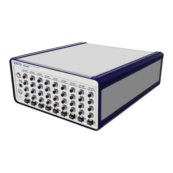
Page 9: Introducing The Iqs-636 Modular Tunable Laser Source Platform
DWDM component testing and optical sensor interrogation. The modular chassis design of the IQS-636, with nine (9) expansion slots, can hold up to thirty six (36) tunable laser sources providing great flexibility to manage the number of laser sources to meet changing laboratory demands. -
Page 10: Features
2. USB 2.0 Connection 7. Mains Power Isolation Switch 3. Ethernet Connection 8. AC Power 100-240V, 50-60Hz 4. Laser Interlock (Output Enable/Disable) 5. *IQS-2800 Expansion Slots (9 Bays) *Note: Your IQS-636 may have IQS-2800 expansion modules already installed. IQS-636 (v4.2) -
Page 11: Hardware Connections
Ethernet. By default the IQS-636 is set to obtain an IP address automatically from a DHCP server. If there is no DHCP server on your network, you will have to configure a static IP for the IQS-636 using the USB connection web interface. - Page 12 8. The units USB connection has a static IP address of 192.168. 96.201, subnet mask 255.255.255.0 9. The USB Ethernet is now configured. Note: Refer to section 12 - USB Connection Web Interface for details on the administrative tasks available over the USB network connection. IQS-636 (v4.2)
-
Page 13: Rack Mounting The Iqs-636 (Optional)
Before mounting the IQS-636, remove all IQS-2800 tunable lasers sources AUTION Make sure ALL cables that are connected to the IQS-636 are removed before attempting to mount the IQS-636 within the instrument rack. MPORTANT Fasteners will be required to attach the IQS-636 to the instrument rack. -
Page 14: Connecting Optical Output
EXFO uses good quality connectors in compliance with EIA-455-21A standards. To keep connectors clean and in good condition, EXFO strongly recommends inspecting them with a fiber inspection probe before connecting them. Failure to do so will result in permanent damage to the connectors and degradation in measurements. -
Page 15: Operating The Iqs-636
636 enough time to finish boot procedures and initialize the communication server. To power off the IQS-636 press the Power On/Off switch. The switch will no longer be illuminated to show the instrument is off. Remote Operation of the IQS-636... -
Page 16: Installing The Software
Modular Tunable Laser Source Platform IQS-636 7. Installing the Software MPORTANT Make sure the client PC is connected to the same network as the IQS-636 and the IQS-636 is also powered on before proceeding with software installation. Client System Minimum Requirements †... -
Page 17: Tunable Instrument Manager
Figure 7 - Tunable Instrument Manager Start-up Device Select Note: If there are no devices listed in the ‘Discovered devices’ list, refer to section Discover for instruction on how to detect your IQS-636 devices. Tunable Instrument Manager Interface 1. Device Selection 2. -
Page 18: Main Display
Modular Tunable Laser Source Platform IQS-636 Main Display The Main Display is the primary information panel of the software interface. It displays the IQS-636 device and all the installed modules in a format that simulates the configuration of the actual device. 1. IQS-2800 Module 2. -
Page 19: Laser Selection Control
1 - 4, 6, 9. This will select lasers 1, 2, 3, 4, 6 and 9. Laser(s)’ edit box content change accordingly. 1, 3 – 6. This will select lasers 1, 3, 4, 5 and 6. Laser numbers for multiple IQS-636 systems are sequential. Laser Output Control... - Page 20 Start + (Step), Start + (2*Step), Start + (3*Step). Note: The software will provide a warning when you attempt to ‘Set’ values that are not valid or out of the operating range of the laser sources. IQS-636 (v4.2)
-
Page 21: Tool Buttons
IQS-636 devices. Scanned devices will show up in the ‘Discovered devices’ list. Click and drag the desired IQS-636 devices to the ‘Selected devices’ list to enable Figure 16 - IQS-636 Device Discovery management of these devices. - Page 22 Modular Tunable Laser Source Platform IQS-636 Load To change to a previous configuration for the current IQS-636. Click ‘Load’ and the ‘Open’ dialog will appear. Navigate to the desired configuration folder and select the desired configuration file then click ‘Open’.
-
Page 23: System Update
‘Current versions’ panel. System Update To perform an update of an IQS-636 system: 1. Select the target system from the ‘Select System’ drop down menu. 2. Make sure the ‘System’ radio button is selected in the ‘Select Target’ panel. -
Page 24: Installing An Iqs-2800 Expansion Module
IQS-636 9. Installing an IQS-2800 Expansion Module ARNING DO NOT attempt to remove or adjust any component of the IQS-636 while the power is on. Make sure you follow the correct procedures below and power down the IQS-636 first. AUTION †... - Page 25 Remove the IQS-2800 from packaging 4. Unpack the IQS-2800 module from the antistatic packaging, making sure to store the packaging near the IQS-636 so it is available to safely store any IQS-2800 that may be removed in the future. Figure 24 - Remove and store Antistatic Packaging Insert the IQS-2800 securing into place 5.
- Page 26 Figure 29 - Powering On the IQS-636 MPORTANT After powering on the IQS-636, please wait at least 2 minutes before attempting to communicate with the instrument. This will allow the IQS- 636 enough time to finish boot procedures and initialize the communication server.
-
Page 27: Removing An Iqs-2800 Expansion Module
Acquire storage electrostatic packaging and blanking module 1. In preparation for removal of the IQS-2800 module, locate and retrieve the antistatic packaging the IQS-2800 was supplied in. This should have been stored near the IQS-636 when the IQS-2800 was installed. - Page 28 IQS-2800. If the IQS-2800 is not stored correctly it may be affected by ESD. The specifications of the IQS-2800 are only valid when all slots have blanking modules. Power down the IQS-636 3. Press the Power On/Off switch. The switch will no longer be illuminated indicating that the instrument is off.
- Page 29 Figure 37 - Fasten screw under Release Latch Power on the IQS-636 10. Power on the IQS-636 by pressing the Power On/Off switch. The switch will become illuminated to verify that the instrument is powered on.
- Page 30 Modular Tunable Laser Source Platform IQS-636 MPORTANT After powering on the IQS-636, please wait at least 2 minutes before attempting to communicate with the instrument. This will allow the IQS-636 enough time to finish boot procedures and initialize the communication server.
-
Page 31: Programming Guide
Information is exchanged in the form of messages. These messages are held in input and output queues. The output queue stores responses to query commands. The IQS-636 transmits any data in the output queue when a read request is received. -
Page 32: Common Command Summary
Query the Operation Complete status Parameters None Response 1: If the IQS-636 and all IQS-2800 modules are ready to execute commands. 0: If the IQS-636 or any IQS-2800 modules still have commands in the input queue to be executed. Example *OPC? -> 0 Command... -
Page 33: Specific Command Summary
Modular Tunable Laser Source Platform IQS-636 Specific Command Summary Table 3 - IQS-636 SCPI Specific Commands Slot commands Description :SLOT[n] :OPC? -Query the status of the Operation Complete bit :OPTions? -Query the modules installed on the slot :IDN? -Query the Identifier for the slot; returns the manufacturer, part number,... -
Page 34: Specific Command Descriptions
Get the Identifier for the slot Parameters None Response Comma separated string containing the <manufacturer>, <part number>, <serial number>,<hardware version><firmware version> Example SLOT1:IDN? -> “EXFO,IQS-2800-1-2-A-S-89,CSL-1186,HW1.0FW0.8” Note: Hardware and firmware versions are combined and not separated by a comma Configuration Commands Command :OUTPut[n]:CHANnel[m]:POWer:UNIT? Syntax :OUTPut[n]:CHANnel[m]:POWer:UNIT? - Page 35 ALL: Returns all of the above parameters Response Returns the minimum, maximum or currently set value for the laser wavelength as specified by parameters. The lock parameter will return as TRUE or FALSE Example SOUR1:CHAN1:WAV? MAX -> 1.561419e-06 IQS-636 (v4.2)
- Page 36 MIN: Get the minimum programmable value MAX: Get the maximum programmable value ALL: Returns all of the above parameters Response Returns the minimum, maximum or currently set fine tuning frequency for the laser as specified by parameters. Example SOUR1:CHAN1:FREQ:FINE? -> 2.00000000e+06 IQS-636 (v4.2)
- Page 37 Returns the current state of the SBS dither Example SOUR1:CHAN1:SBS? -> ON Command :SOURce[n]:CHANnel[m]:SBS:STATE Syntax :SOURce[n]:CHANnel[m]:SBS[:STATE]<wsp>[ON|OFF] Description Set the state of the SBS dither Parameters ON|OFF: Set the SBS dither state to on or off Response None Example SOUR1:CHAN1:SBS:STATE ON IQS-636 (v4.2)
- Page 38 Returns the minimum, maximum or currently set SBS dither frequency for the laser as specified by parameters Example SOUR1:CHAN1:SBS:FREQ? -> 1.00000000e+08 Command :SOURce[n]:CHANnel[m]:TEMPerature? Syntax :SOURce[n]:CHANnel[m]:TEMPerature? Description Get the laser temperature Parameters None Response Numerical temperature in degrees Celsius Example SOUR1:CHAN1:TEMP? -> 26.88 IQS-636 (v4.2)
-
Page 39: Visa Programming Example: Matlab
Objects’ entry in the ‘Instrument Control Toolbox’. Figure 39 - MATLAB Test and Measurement Tool 3. Right click on ‘Interface Objects’ to bring up the context menu. Now select ‘Create New Interface Object…’ Figure 40 - MATLAB Create New Interface Object IQS-636 (v4.2) - Page 40 Figure 41 - MATLAB New Object Creation Window Then click ‘OK’ 5. Once the VISA object is created you can click ‘Connect’ which will open the connection to the IQS-636 ready for communication. Figure 42 - MATLAB VISA Object Connect 6. While connected, using the ‘Communicate’...
-
Page 41: Matlab Example Code: Query The Iqs-636
% Close the connection to the object fclose(IQS_636); % Clean up all objects. delete(IQS_636); Notes: The IP address ( ) used in the code is an example only. You will need to 192.168.1.4 substitute in the IP address of your IQS-636. IQS-636 (v4.2) -
Page 42: Usb Connection Web Interface
Figure 45 - USB Web Interface, Welcome Screen Network Configuration (Ethernet) The Ethernet IP address for the IQS-636 is requested from a DHCP server by default (Obtain an IP address automatically), however if no DHCP server is available, the configuration of the IQS-636 Ethernet networking must be performed using this USB web interface. -
Page 43: Download Log File
Modular Tunable Laser Source Platform IQS-636 Download Log File If a copy of the IQS-636 system log files is required, the Download log file link can be used to retrieve this data. Clicking this link will initiate a download of the logfile.zip. Click ‘Save’... -
Page 44: Maintenance
Recycling and Disposal (Applies to European Union only) For complete recycling/disposal information as per European Directive WEEE 2012/19/UE, visit the EXFO Web site at www.exfo.com/recycle IQS-636 (v4.2) - Page 45 CHINESE REGULATION ON RESTRICTION OF HAZARDOUS SUBSTANCES 中国关于危害物质限制的规定 NAMES AND CONTENTS OF THE TOXIC OR HAZARDOUS SUBSTANCES OR ELEMENTS CONTAINED IN THIS EXFO PRODUCT 包含在本 GZH Q 产品中的有毒有害物质或元素的名称和含量" Indicates that this toxic or hazardous substance contained in all of the homogeneous materials for this part is below the limit requirement in SJ/T11363-2006 表示该有毒有害物质在该部件所有均质材料中的含量均在...
-
Page 46: Technical Support
14. Technical Support Contacting the Technical Support Group To obtain after-sales service or technical support for this product, contact EXFO at one of the following numbers. The Technical Support Group is available to take your calls from Monday to Friday, 8:00 a.m. to 7:00 p.m. (Eastern Time in North America). -
Page 47: Warranty
Exclusions EXFO reserves the right to make changes in the design or construction of any of its products at any time without incurring obligation to make any changes whatsoever on units purchased. Accessories, including but not limited to fuses, pilot lamps, batteries and universal interfaces (EUI) used with EXFO products are not covered by this warranty. -
Page 48: Certification
5. Return the equipment, prepaid, to the address given to you by support personnel. Be sure to write the RMA number on the shipping slip. EXFO will refuse and return any package that does not bear an RMA number. -
Page 49: Exfo Service Centers Worldwide
Tel.: +44 2380 246800 Chandlers Ford, Hampshire S053 4DG Fax: +44 2380 246801 ENGLAND support.europe@exfo.com EXFO Telecom Equipment (Shenzhen) Ltd. 3rd Floor, Building 10, Tel: +86 (755) 2955 3100 Yu Sheng Industrial Park (Gu Shu Crossing), No. 467, Fax: +86 (755) 2955 3101 National Highway 107, support.asia@exfo.com...
Need help?
Do you have a question about the IQS-636 and is the answer not in the manual?
Questions and answers