Table of Contents
Advertisement
Safety, Operation and Maintenance Manual
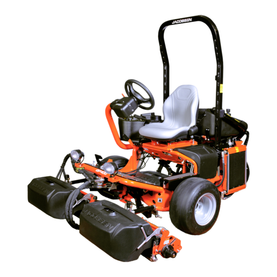
Jacobsen GP400™ Ride on Greens Mower
Engine Range - Kubota D722-E3B D722-E4B
GP400 Gasoline / Series: GZ / Product code:USAG004
GP400 Gasoline (USA only) / Product code:62706
GP400 Diesel (Kubota E3B) / Series: GY / Product code:USAD004
GP400 Diesel (Kubota E4B) / Series: GY4 / Product code:USAD004
GP400 Diesel (Kubota E4B) / Series: GY5 / Product code:USAD004
WARNING: If incorrectly used this machine can cause severe
injury. Those who use and maintain this machine must be
trained in its proper use, warned of its dangers and must read
the entire manual before attempting to set up, operate, adjust
or service the machine.
GB
RJL 100 July 2018
United
Kingdom
Briggs and Stratton Vanguard 350447
WARNING
25000G-GB (rev.6)
When Performance Matters.
™
Advertisement
Table of Contents

Subscribe to Our Youtube Channel
Related Manuals for Textron JACOBSEN GP400


Summary of Contents for Textron JACOBSEN GP400
- Page 1 25000G-GB (rev.6) Safety, Operation and Maintenance Manual Jacobsen GP400™ Ride on Greens Mower Engine Range - Kubota D722-E3B D722-E4B Briggs and Stratton Vanguard 350447 GP400 Gasoline / Series: GZ / Product code:USAG004 GP400 Gasoline (USA only) / Product code:62706 GP400 Diesel (Kubota E3B) / Series: GY / Product code:USAD004...
-
Page 2: Table Of Contents
1 CONTENTS SECTION PAGE SECTION PAGE INTRODUCTION MAINTENANCE AND LUBRICATION Important ..................3 Maintenance And Lubrication Chart........... 54 Product Identification ..............4 Engine Lubrication - Gasoline ........... 54 Guidelines For The Disposal Of Scrap Products ....... 6 Engine Lubrication - Diesel ............56 During Service Life .............. -
Page 3: Important
SAFETY 3 IMPORTANT __________________________________________________________ The JACOBSEN GP400 is available as a Petrol or Diesel engined self propelled Reel mower. The hydraulic systems are for the traction drive, the cutting unit lift and the lower and cutting unit drives and steering. -
Page 4: Product Identification
3 SAFETY PRODUCT IDENTIFICATION ___________________________________________ _ Maximum front axle load in Kg (for machines being driven West Road on the highway) Ransomes Europark Ipswich IP3 9TT Gross weight (mass) in Kg England Maximum rear axle load in Kg (for machines being driven on the highway) Power in Kw Date code... - Page 5 SAFETY 3 Weight of ROPS Date Code West Road Ransomes Europark Standard Used Ipswich IP3 9TT England Part Number Used on Product Serial Number ROPS Serial Plate Location The ROPS serial plate (C) is located at the base of the front of the ROPS main beam.
-
Page 6: Guidelines For The Disposal Of Scrap Products
3 SAFETY 3.3GUIDELINES FOR THE DISPOSAL OF SCRAP PRODUCTS _____________________ 3.3.1 DURING SERVICE LIFE __________ Used oil, oil filters and engine coolant are hazardous materials. Recommended procedures must be followed for their safe removal. If a fluid leaks, contain the spill to make sure that the leak does not flow into the ground or drainage system. Follow the local laws to make sure that leaks are controlled safely. -
Page 7: Parts Manual
SAFETY 3 PARTS MANUAL ______________________________________________________ In compliance with the ISO14001 standard, Ransomes Jacobsen Limited does not send a paper parts manual with every product. To refer to a parts list for this mower you have four options: Website – www.Ransomes Jacobsen.com. Select the “CUSTOMER CARE” tab.You now have access to Parts drawings and lists to help with the identification of spare parts. -
Page 8: Key Numbers
3 SAFETY KEY NUMBERS _______________________________________________________ Record the key numbers shown below: Starter Switch:- - - - - - - - - - - - - - - - - - - - - - - - - - - - - - - - - - - - - - - - - - - - Diesel tank:- - - - - - - - - - - - - - - - - - - - - - - - - - - - - - - - - - - - - - - - - - - - - - Record the machine and engine numbers shown below: The machine serial number is found on the registration plate and the engine serial number can be found on the... -
Page 9: How To Operate Safely
SAFETY 3 HOW TO OPERATE SAFELY _____________________________________________ WARNING EQUIPMENT OPERATED INCORRECTLY OR WITHOUT TRAINING CAN BE DANGEROUS. Know the location and correct operation of controls. Operators without experience must receive instruction from another person that knows the correct operation of the equipment before you operate the mower. Only use parts, accessories and attachments approved by Jacobsen. -
Page 10: Operation
3 SAFETY 3.1.3 Operation Never operate the engine without enough ventilation or in an enclosed area. The carbon monoxide in the exhaust fumes can increase to dangerous levels. Never carry passengers. Keep other persons or animals away from the mower. Disengage all drives and engage the parking brake before you start the engine. -
Page 11: Rops
SAFETY 3 3.1.4 ROPS The ROPS is a safety device. Keep the ROPS in the vertical and locked position. Always use the seat belt when you operate the mower. Make sure the seat belt can be released quickly in an emergency. Only operate the mower with the ROPS in the folded position on flat and level surfaces when necessary. -
Page 12: When You Put The Mower On A Trailer
3 SAFETY Charge the battery in an area with good airflow. The battery can release hydrogen gas that is explosive. To prevent an explosion, keep any device that can cause sparks or flames away from the battery. Disconnect the battery charger from the power supply before you connect or disconnect the battery charger to the battery. -
Page 13: Important Safety Notes
SAFETY 3 3.1.8 Important Safety Notes This safety alert symbol is used to alert you to possible hazards. DANGER: Indicates a dangerous condition that WILL cause death or injury unless it is prevented. WARNING: Indicates a dangerous condition that CAN cause death or injury unless it is prevented. CAUTION: Indicates a dangerous condition that can cause injury and property damage unless it is prevented. - Page 14 3 SAFETY WARNING California Proposition 65 Engine Exhaust, Some Of Its Constituents, And Some Vehicle Components Contain Or Release Chemicals Known To The State Of California To Cause Cancer And Birth Defects Or Other Reproductive Harm. WARNING To Prevent Injury From The Hot Oil At High Pressure, Do Not Use Your Hands To Check For Oil Leaks. Make Sure That You Use Paper Or Cardboard.
- Page 15 SAFETY 3 WARNING Vibration Exposure Limits Exposure limits are calculated as a combination of the vibration level (magnitude) of the tool and the Daily Exposure Time (Trigger Time). E.g. A product with 5m/s² vibration can be used up to 2 hours/day to reach the EAV and up to 8 hours/day to reach the ELV.
-
Page 16: Specification
4 SPECIFICATIONS ENGINE SPECIFICATION ______________________________________________ Kubota Model D722-E3B D722-E4B Type Vertical, water-cooled, 4-cycle diesel engine. Number of Cylinders Bore & Stroke 67mm x 68mm (2.64 x 2.68) Total Displacement 719cm³ Combustion Chamber Spherical type (E-TVCS) Spherical type (E-TVCS,NA) Gross Intermittent Power 13.2kW (17.7hp) @ 3200rpm Maximum Speed: 3400 ±... -
Page 17: Dimensions & Weights
SPECIFICATIONS 4 4.2 DIMENSIONS & WEIGHTS ________________________________________________ Width of Cut: 160 cm 63 inches Overall Width Cutting: 188 cm 74 inches Overall Width Transport (minimum): 186 cm 73.25 inches Overall Height with ROPS Frame: 196.5 cm 77.38 inches Overall Length Without Grass Boxes: 219 cm 86.2 inches Overall Length With Grass Boxes:... -
Page 18: Machine Specification
4 SPECIFICATIONS TYRE PRESSURE Front Wheel Rear Wheel Product Tyre Size Tyre Type Tyre Pressure Tyre Size Tyre Type Tyre Pressure 0.7 bar 0.7 bar GP400 20 x 10.00 - 10 OTR Smooth 20 x 10.00 - 10 OTR Smooth (10 psi) (10 psi) MACHINE SPECIFICATION _____________________________________________... -
Page 19: Vibration Level
SPECIFICATIONS 4 VIBRATION LEVEL ___________________________________________________ The machine was tested for hand/arm vibration levels. The operator was in the normal position to drive the vehicle, with two hands on the steering mechanism. The engine was in operation and the cutting device was in rotation, while the machine was not moving. -
Page 20: Noise Level
4 SPECIFICATIONS NOISE LEVEL________________________________________________________ The Machinery Safety Directive 2006/42/EC Exposure Of Workers To The Risks Arising From Physical Agents (Noise) Directive 2003/10/EC By compliance to: The Lawnmower Standard BS EN ISO 5395:2013 Sound Pressure Standard EN ISO 3746: 2010 GP400 Gas Measured Sound Pressure 82 dB(A) ± 0.86 LWA GP400 Diesel Measured Sound Pressure 86 dB(A) ±... -
Page 21: Cutting Unit Specification
SPECIFICATIONS 4 CUTTING UNIT SPECIFICATION_________________________________________ 7 Blade 9 Blade 11 Blade 15 Blade Verticut Construction Fabricated steel construction 559mm (22 559mm (22 559mm (22 559mm (22 559mm (22 Reel Length Number of Knives Number of Blades Reel Diameter (New) 127mm (5 in) 127mm (5 in) 127mm (5 in) 127mm (5 in) -
Page 22: Recommended Lubricants
4 SPECIFICATIONS RECOMMENDED LUBRICANTS _________________________________________ Engine oil: Diesel:Should be to MIL-L-2104C or to A.P.I. Classification CD grades. [10W-30] Gasoline:Should be to MIL-L-2104C or to A.P.I. Classification SE/SF grades. [10W-30] TEMPERATURE VISCOSITY Above 4°C (39°F) SAE30 Below 4°C (39°F) SAE5W-30 or SAE10W-30 Grease: For rear axle: K NATE (RJL No. -
Page 23: Certificates Of Conformity
SPECIFICATIONS 4 4.11 CERTIFICATES OF CONFORMITY _______________________________________ Ransomes Jacobsen Limited West Road, Ransomes Europark, Ipswich, England, IP3 9TT USAD004 USAG004 Jacobsen GP 400 Ride on Reel Mower GY000301 - GY999999 GY400301 - GY499999 GZ000301 - GZ999999 Kubota D722-ET04 and D722-EF01 Briggs &... - Page 24 4 SPECIFICATIONS GP400 Gas with Standard Cutting reels 82 dB(A) ± 0.74 Leq (2006/42/EC) GP400 Gas with Standard Cutting reels plus Groomer and brush kit 83 dB(A) ± 0.74 Leq (2006/42/EC) GP400 Diesel with Standard Cutting reels 86 dB(A) ± 0.74 Leq (2006/42/EC) GP400 Diesel with Standard Cutting reels plus Groomer and brush kit 86 dB(A) ±...
- Page 25 SPECIFICATIONS 4 Ransomes Jacobsen Limited West Road, Ransomes Europark, Ipswich, England, IP3 9TT Product Code Serial Number Description 67135 Cutting Unit, 11 blade, Greens 67136 Cutting Unit, 9 blade, Greens 67137 Cutting Unit, 7 blade, tees 67138 Cutting Unit, Verticut 62834 6283401651 ~ 6283402999 GP400 22 in.
- Page 26 4 SPECIFICATIONS Partly completed machinery must not be put into service until the final machinery into which it is to be incorporated has been declared in conformity with the provisions of Directive 2006/42/EC. Delvist fremstillede maskiner må ikke indsættes i driften, før den endelige maskine, som den skal inkorporeres i, er blevet erklæret I overensstemmelse med bestemmelserne i Direktiv 2006/42/EF. Gedeeltelijk voltooide machinerie mag niet in dienst worden genomen, totdat er voor de definitieve machinerie, waarvan gedeeltelijk voltooide machinerie onderdeel uitmaakt, een conformiteitsverklaring is ontvangen onder de voorwaarden van Richtlijn 2006/42/EG.
-
Page 27: Notes
SPECIFICATIONS 4 NOTES en-27... -
Page 28: Decals
DECALS SAFETY DECALS_____________________________________________________ en-28... - Page 29 5 DECALS Read Operator's Manual. Keep a Safe Distance from the Machine. Maximum permissible working slope. (See Accessories section for correct limit with various accessories). Seat Belt Must be Worn When ROPS is Deployed. Do Not Wear Seat Belt When ROPS is Lowered. Read Operators Manual.
-
Page 30: Instruction Decals
DECALS INSTRUCTION DECALS USE LOW OR ULTRA-LOW SULPHUR FUEL ONLY Speed Control (Foot Pedal) Engine Speed Control. Parking Brake ‘P’. Maximum Sound Power Level. Jacking Point Centre Unit raise / Lower Speed Adjustment Use Low Or Ultra-low Sulphur Fuel en-30... -
Page 31: Notes
5 DECALS NOTES en-31... -
Page 32: Controls
CONTROLS OPERATOR WORKSTATION____________________________________________ en-32... -
Page 33: Instrument Panel
6 CONTROLS INSTRUMENT PANEL _________________________________________________ GASOLINE Starter Key Switch Throttle Control Lever Cutting Unit Switch (PTO) Joystick Working Lights Blanking Plug Hour Meter Blocked Hydraulic Filter Warning Light Ignition Warning Light Choke Control Mow / Transport Lever Power Outlet Engine Oil Pressure Horn DIESEL Starter Key Switch... -
Page 34: Starter Key Switch
CONTROLS 6.2A STARTER KEY SWITCH _______________________________________________ The key switch has three positions: OFF - prevents all electrical functions from operating. Switch must be in the OFF position to remove the key. ON - Illuminates the red indicator lamp. This position is also for normal operation. -
Page 35: Engine Coolant Temperature (Diesel Only)
6 CONTROLS 6.2D CUTTING UNIT SWITCH (PTO)__________________________________________ The Mow/ Lift Joystick lowers and raises the cutting heads. To Lower the Heads: Move the joystick forwards (A) to lower the cutting heads. If reel enable switch is on, reel rotation starts when the heads are lowered. -
Page 36: Blocked Hydraulic Filter Warning Light
CONTROLS 6.2H BLOCKED HYDRAULIC FILTER WARNING LIGHT __________________________ Monitors Hydraulic filter condition. Coloured yellow, Illuminates prior to filter bypass valve operating, when illuminated filter requires changing. Under cold start conditions the LED may illuminate for 15 - 20 minutes until the hydraulic oil reaches normal operating temperature. -
Page 37: Mow / Transport Lever
6 CONTROLS 6.2L MOW / TRANSPORT LEVER ____________________________________________ This lever limits the maximum traction speed for cutting and allows engagement of reels. 6.2M POWER OUTLET _____________________________________________________ Provides a 12 volt 10amp power supply for accessories. 6.2N HORN BUTTON ______________________________________________________ Situated on rear of the control panel. Press to sound warning. -
Page 38: Traction Pedal
CONTROLS TRACTION PEDAL ____________________________________________________ The Direction/Speed Pedal controls speed and direction. Depress front of pedal (A) to go forward, depress back of pedal (B) to go backward. Increased movement of the pedal will increase speed. To slow and stop the machine, ease the pedal back to the neutral position. -
Page 39: Free Wheel
6 CONTROLS FREE WHEEL ________________________________________________________ To push the machine, disengage the parking brake Turn screw (A) located on the underside of the transmission pump 180º counterclockwise. Set the steering wheel so that the rear wheel is pointing straight ahead. After pushing the machine, return the screw (A) on the pump to its operating position. -
Page 40: Operation
OPERATION DAILY INSPECTION ___________________________________________________ CAUTION The Daily Inspection Should Be Performed Only When The Engine Is Off And All Fluids Are Cold. Lower Implements To The Ground, Engage Parking Brake, Stop Engine And Remove Ignition Key. Perform a visual inspection of the entire unit, look for signs of wear, loose hardware and missing or damaged components. -
Page 41: Operating Procedure
7 OPERATION Test 2: The engine must not start if the mower engage device is on. Test 3: The engine must not start if the parking brake is not applied. Test 4: Start the engine in the normal manner, then turn mower engage device on and lift your weight off the seat. - Page 42 OPERATION Disengage the cutter motors and raise the implements when crossing paths or roads. Look out for traffic. CAUTION Remove All Debris From The Site Before Mowing. Enter A New Area Cautiously Always Operate At Speeds That Allow You To Have Complete Control Of The Mower.
-
Page 43: Setting Up The Machine
7 OPERATION SETTING UP THE MACHINE ____________________________________________ WARNING Setup procedures must be performed as specified by properly trained service personnel only. Check the hydraulic system. Make sure the connections are tight and all hoses and lines are in good condition before pressurizing the system. -
Page 44: Mounting The Cutting Heads
OPERATION MOUNTING THE CUTTING HEADS ______________________________________ Review the "OPERATION" section before mounting the cutting units. NOTE: All Ransomes Jacobsen cutting heads are backlapped at the factory, but the bedknife adjustment must be performed before the unit is put into use. Refer to the Bedknife Adjustment Procedure as described in section 8.4 in this manual. -
Page 45: Reel Motor Mounting
7 OPERATION REEL MOTOR MOUNTING _____________________________________________ The cutting head motor mounting adaptor, coupling and hardware are shipped in the step located above the left front wheel. Install a 1.49" i.d. x .07" (38mm x 1.7mm) O-ring on the male side of motor adapter plate and a 1.99"... -
Page 46: Cutting Cylinder Lift & Lower Synchronisation
OPERATION CUTTING CYLINDER LIFT & LOWER RATE & SYNCHRONISATION____________ The valves that control the rate and sequence in which the cutting units rise and fall are set at the factory, how- ever they can be reset or altered using the following steps. Start the machine and run the engine at full throttle for 15-20 minutes to ensure that the oil is at the optimum temperature. -
Page 47: Starting The Engine
7 OPERATION STARTING THE ENGINE _______________________________________________ The following procedure is for starting cold engines. Ensure the FWD/REV pedal is in the neutral position, the mow switch is off, the throttle setting is in a mid position. Turn the ignition switch fully clockwise and hold until the engine starts (approximately 5-10 sec.) The glow plugs are auto timed depending on the coolant temperature for operating the starter motor (This should only take a few seconds) When the engine starts, release the key immediately and it will return to the RUN position. -
Page 48: To Stop The Engine
OPERATION Each successive pass should overlap the previous one by two or three inches (51 or 76mm) (a painted mark two or three inches (51 or 76mm) in from the outer edges of the two front grass catchers will help align each overlapping pass). -
Page 49: Backlapping
7 OPERATION use the Ransomes Jacobsen “Cutting Unit Tool” part number 4184540 See below or stout stick, put into the cutting cylinder between the blades. Rotate the cylinder with either the “Cutting Unit Tool” or “Stout Stick” until the obstruction has been removed. -
Page 50: Backlapping Procedure
OPERATION 7.15 BACKLAPPING PROCEDURE __________________________________________ Before starting the backlap procedure, release the centre unit and swing it out. The backlap valve is located under the seat plate on the right hand side. It can be accessed from under the machine when the centre unit is swung out Apply an even coat of backlapping compound to the entire length of each blade of the reels. -
Page 51: Mowing On Slopes
7 OPERATION 7.18 MOWING ON SLOPES _________________________________________________ The mower has been designed for good traction and stability under normal mowing conditions. Use caution when operating on slopes, especially when the grass is wet. Wet grass reduces traction and steering control. WARNING To Minimize The Possibility Of Overturning, The Safest Method For Operating On Hills... - Page 52 OPERATION WARNING When The Machine Is Being Used, Whether Cutting Grass Or Not, On Slopes, The ROPS Frame Should Be Deployed And The Seat Belt Used.this Rationale Is Based On The Fact 16° Maximum That A Seat Belt Must Be Worn With A ROPS To Comply With The Machiney Directive 2006/42/EC Sections 3.2.2, Seating &...
-
Page 53: Slope Calculation Chart
7 OPERATION SLOPE CALCULATION CHART Use Either of these columns but not both The result of what you are measuring Height ‘C’ in inches Height ‘C’ in millimeters Slope Angle ‘D’ Slope Angle ‘D’ measured with a 1 yard measured with a 1 metre measured in Degrees measured in horizontal edge ‘A’... -
Page 54: Maintenance And Lubrication
MAINTENANCE & LUBRICATION MAINTENANCE AND LUBRICATION CHART ______________________________ GASOLINE MAINTENANCE AND LUBRICATION CHART Interval Item First 5-8 hours Change Engine Oil. Daily Check Engine Oil Level. 10 hours Check Safety Interlock System. Check Hydraulic Fluid Level. ... - Page 55 8 MAINTENANCE & LUBRICATION FLUID REQUIREMENTS Quantity Type Engine Oil (with filter) 1.4 litres SAE30, SAE5W 30, 10W 30 Hydraulic Oil (with filter) 22 litres GreensCare ISO VG 46 Fuel 55 litres Lead Free Minimum 85 Octane en-55...
-
Page 56: Engine Lubrication - Diesel
MAINTENANCE & LUBRICATION DIESEL MAINTENANCE AND LUBRICATION CHART Interval Item First 50 hours Change Engine Oil & Filter. Check Fan Belt Tension. Change Hydraulic Oil Filter. Daily Check Engine Oil Level. 10 hours Check Safety Interlock System. ... - Page 57 8 MAINTENANCE & LUBRICATION FLUID REQUIREMENTS Quantity Type Engine Oil (with filter) 3.2 litres 10W 30 Hydraulic Oil (with filter) 40 litres GreensCare ISO VG 46 Radiator Coolant 3.8 litres 50% Anti-Freeze Fuel 55 litres No 2-D (ASTM D975) Diesel en-57...
-
Page 58: Engine Access
MAINTENANCE & LUBRICATION ENGINE ACCESS _____________________________________________________ The Fuel & Hydraulic Tanks can be raised for better access to the engine. Tilt the seat forwards. Turn fuel tap OFF (C) (Gasoline machines only) Loosen the locking hand wheel (A), under the tank above the rear axle. -
Page 59: Engine Oil Change- Gasoline
8 MAINTENANCE & LUBRICATION ENGINE OIL CHANGE- GASOLINE ______________________________________ Change engine oil. After first warming up the engine remove the drain plug and drain all the oil from the crankcase sump. Clean plug and replace. Remove the filler cap (1) and refill with fresh oil up to the maximum level on the dipstick (2). -
Page 60: Air Filter - Gasoline
MAINTENANCE & LUBRICATION AIR FILTER - GASOLINE _______________________________________________ NOTICE DO NOT use bent or dented air cleaner housing. DO NOT use bent or dented air cleaner elements. IMPORTANT! WE RECOMMEND THAT THE FILTER ELEMENT BE REPLACED BEFORE ENGINE PERFORMANCE IS AFFECTED. -
Page 61: Engine Fuel Filter - Gasoline
8 MAINTENANCE & LUBRICATION ENGINE FUEL FILTER - GASOLINE ______________________________________ Replace fuel filter (a) Release clamp bands either side of in-line filter (A) and remove fuel pipes. (b) Fit new in-line filter (A) to fuel pipes and replace clamp bands. A. - Page 62 MAINTENANCE & LUBRICATION ENGINE LUBRICATION - DIESEL ________________________________________ Check Engine Oil Level Check the engine oil level before starting or more than five minutes after stopping the engine. With the machine on level ground, remove the dipstick 1, wipe it clean and replace. Take the dipstick 1 out again, and check the oil level.
-
Page 63: Air Filter - Diesel
8 MAINTENANCE & LUBRICATION 8.10 AIR FILTER - DIESEL__________________________________________________ Clean Air Filter Element Note: Check the air filter condition indicator situated on the underside of the outlet elbow at regular intervals. If the indicator shows red either clean or replace the air filter element. -
Page 64: Engine Coolant - Diesel
MAINTENANCE & LUBRICATION 8.12 ENGINE COOLANT - DIESEL Check Engine Coolant Level The level of coolant in the expansion tank (C) should be between the MAX and MIN level indicators when cold. If topping up is required, remove the plastic cap and top up using the correct anti-freeze mixture. -
Page 65: Oil Cooler And Radiator - Diesel
8 MAINTENANCE & LUBRICATION 8.13 OIL COOLER AND RADIATOR - DIESEL __________________________________ Release the 6 Swell latches (D) holding the radiator/ oil cooler Louvers (E) to the cowling. Remove screen and clean. Remove any debris from inside of cowling and around oil cooler and radiator F. -
Page 66: Bleeding The Fuel System - Diesel
MAINTENANCE & LUBRICATION 8.14 BLEEDING THE FUEL SYSTEM - DIESEL _________________________________ The fuel system must be bled when: • Starting the engine for the first time. • The fuel tank becomes completely empty. • The engine has not been used for an extended period of time. -
Page 67: Air Cleaner - Diesel
8 MAINTENANCE & LUBRICATION 8.15 AIR CLEANER - DIESEL _______________________________________________ Changing the air filter NOTE:After 6 cleanings replace the filter element. (a) Remove end cap of air filter cartridge. (b) Remove loose dirt from element with compressed air working from the clean to dirty side, using compressed air max 6 bar, with nozzle 5cm from element. -
Page 68: Hydraulic System - Gas & Diesel
MAINTENANCE & LUBRICATION 8.17 HYDRAULIC SYSTEM - GAS & DIESEL ___________________________________ Check Hydraulic Oil Level Check hydraulic oil level using sight gauge (C). Change Hydraulic Oil Clean around hose in bottom of Hydraulic tank and remove. Allow tank to drain into a suitable container and replace hose. -
Page 69: Handbrake - Gas & Diesel
8 MAINTENANCE & LUBRICATION 8.18 HANDBRAKE - GAS & DIESEL __________________________________________ Place the front axle on axle stands and remove the front wheels. Inspect the discs and pads for wear and replace if necessary. Remove all debris from around the brake assembly and ensure the calliper is free to float. -
Page 70: Machine Maintenance General - Gas & Diesel
MAINTENANCE & LUBRICATION 8.20 MACHINE MAINTENANCE GENERAL - GAS & DIESEL ______________________ Other Regular Service. • Verify proper operation of safety interlock switches (Seat switch, etc.) • Ensure nuts and bolts remain tight. • visually inspect for hydraulic leaks. • Keep engine bay clear of debris. -
Page 71: Notes
8 MAINTENANCE & LUBRICATION NOTES en-71... -
Page 72: Adjustments
ADJUSTMENTS TRACTION CONTROL PEDAL ___________________________________________ ADJUSTING MOW SPEED To determine mow speed, run a time check on how fast the unit travels in a distance of 50’ (15.24 M). Prepare a level surface with enough room to start and end beyond the 50’ marks. -
Page 73: Adjusting Speed Control Switch
9 ADJUSTMENTS ADJUSTING SPEED CONTROL SWITCH __________________________________ The speed control sensor is positioned under the control panel. The mechanism is activated when the speed con- trol lever is cycled from the transport and mow positions. To set the sensor (A), position the control lever in the “mow”... -
Page 74: Rear Swing Out Arm
ADJUSTMENTS REAR SWING OUT ARM ________________________________________________ NOTE:The rear swing out arm is to allow you easy access to the rear cutting head. The cutting heads must be in the raised position. DO NOT swing the arm out with the cutting heads in the lowered position. -
Page 75: Levelling Linkage For The Front Cutting Heads
9 ADJUSTMENTS LEVELLING LINKAGE FOR THE FRONT CUTTING HEADS ___________________ NOTICE • The dimensions in the figure are factory preset and the levelling linkage should not need adjusting. After some time the linkage may require some adjusting. If it is required, only make adjustments on the adjusting connector (E). -
Page 76: Seat Adjustment
ADJUSTMENTS SEAT ADJUSTMENT ___________________________________________________ Milsco XB200 Pull out on the adjustment lever located under the left side of the seat. Slide the seat to the desired position and release the lever. Grammer MSG 65 Safety Driver's seats that have been adjusted incorrectly have a smaller moving area. In order to prevent any personal injury, the seat must be adjusted for the driver's weight To prevent injury, no objects should be placed within the moving area of the driver's seat. - Page 77 9 ADJUSTMENTS If you notice that the seat does not function correctly (for example a defective suspension of the driver's seat; improper curvature of the lumbar support or damaged bellows), contact a specialist workshop immediately to arrange for repairs to be carried out. If you fail to do so, your health may be affected and the risk of an accident increased.
- Page 78 ADJUSTMENTS Fore/aft adjustment The fore/aft adjustment is released by lifting the locking lever. WARNING Risk of accident. Do not operate the locking lever while driving. WARNING Risk of crushing. only touch the lever at the indented grip, do not reach back under the lever. •...
- Page 79 9 ADJUSTMENTS Armrests The armrests can be folded back if required and the height individually adjusted. To adjust the armrests for height, sep- arate the round cap (see arrow) from the cover, loosen the hexagon nut (size 13 mm) behind it and adjust the armrests to the desired position (5-steps) and tighten the nut again (25Nm).
- Page 80 ADJUSTMENTS DANGER When The Machine Is Being Used Off Road, Whether Cutting Grass Or Not, The Seat Belt Should Only Be Worn When A Rops Frame Is In Place And Deployed. This Rationale Is Based On The Fact That A Seat Belt Must Be Worn With A ROPS To Comply With The Machinery Directive 98/37/EC Sections 3.2.2, Seating &...
-
Page 81: Bedknife-To-Reel Trueset™ Reel
9 ADJUSTMENTS ADJUSTMENTS BEDKNIFE-TO-REEL TRUESET™ REEL ___________________________________ (Pre-adjustment Check) 1. Check the reel bearings for end play or radial play. There should be no end play or radial play. See Section 4.9. CAUTION To prevent personal injury and damage to the cutting edges, wear gloves and handle the reel and bedknife with extreme care. -
Page 82: Bedknife Adjustment Trueset™ Reel
ADJUSTMENTS BEDKNIFE ADJUSTMENT TRUESET™ REEL_______________________________ 1. Read Section 9.7 before making the adjustment. 2. Start adjustment at the leading end of the reel, followed by the trailing end. The leading end of the reel blades is that end which passes over the bedknife first during normal reel rotation. 3. -
Page 83: Cutting Height Trueset™ Reel
9 ADJUSTMENTS CUTTING HEIGHT TRUESET™ REEL _____________________________________ Note: Always make the reel to bedknife adjustment before adjusting height of cut. (Sections 9.7 and 9.8). 1. Set desired cutting height on the gauge (E). a. Measure distance between the underside of screw head and gauge block surface (F). b. -
Page 84: Reel Beartrueset™ Reel
ADJUSTMENTS 9.10 REEL BEARING TRUESET™ REEL _______________________________________ Any radial play or excessive end play indicates bad bearings, a weak tension spring or a backed off nut. 1. Check bearing housing mounting hardware. Tighten or replace components as required. Carefully clean threads with degreaser. -
Page 85: Bedknife Adjuster Tension Trueset™ Reel
9 ADJUSTMENTS 9.12 BEDKNIFE ADJUSTER TENSION TRUESET™ REEL_________________________ NOTICE Over tightening slotted nut (S) will make bedknife adjuster rod (T) difficult to adjust. Remove cotter pin (U) and fully loosen, then tighten slotted nut (S) to remove clearance (no end play) between components. -
Page 86: Bedknife Adjustment Classic Xp™ Reels
ADJUSTMENTS 9.14 BEDKNIFE ADJUSTMENT CLASSIC XP™ REELS ___________________________ Any adjustment to the clearance between the reel blades and the bedknife should be done at the leading end of the reel first (the end at which each individual blade first crosses the bedknife). Then at the opposite end of the reel. Loosen the lower adjustment screws at each end by turning them approximately 1/4 turn counterclockwise. -
Page 87: Height Of Cut Classic Xp™ Reels
9 ADJUSTMENTS 9.15 HEIGHT OF CUT CLASSIC XP™ REELS ___________________________________ Work Bench Setting NOTE: All three cutting heads MUST be accurately set at the same height of cut to insure an even cut. Bedknife adjustment must be made before setting the height of cut. -
Page 88: Accessories
10 ACCESSORIES 10.1 THREE WHEEL DRIVE KIT _____________________________________________ Kit number LMAC418 10.4 10.2 PADDLE KIT _________________________________________________________ kit Number LMAC412 10.5 en-88... -
Page 89: Dew Whip Kit
10 ACCESSORIES 10.3 DEW WHIP KIT________________________________________________________ Kit number LMAC415 10.6 10.4 GROOMER KIT _______________________________________________________ Kit number 6.3mm spacing: 067912 Kit number 12.7mm spacing: 067914 en-89... -
Page 90: Notes
10 ACCESSORIES NOTES en-90... -
Page 91: Problem Solving
11 PROBLEM SOLVING 11.1 PROBLEM SOLVING GENERAL ___________________________________________________ Problems Possible Causes Action The glow plug has not timed out Reset the ignition switch and allow the glow plug to time out before cranking engine. Battery low on charge or Inspect the condition of battery and battery connections. defective. -
Page 92: Quality Of Cut
12 QUALITY OF CUT 12.1 QUALITY OF CUT TROUBLESHOOTING __________________________________ It is recommended that a “test cut” be performed to 1. Mowing (Ground) Speed. evaluate the mower’s performance before beginning 2. Reel Bearing Condition and Pre-Load (End Play) repairs. Adjustment. An area should be available where “test cuts”... -
Page 93: Marcelling
12 QUALITY OF CUT 12.3 MARCELLING ________________________________________________________ Marcelling, like washboarding, is a cyclical pattern of varying cutting heights, resulting in a wave-like cut appearance. In most cases, the wave tip-to-tip distance is 2 in. (5 cm) or less. TN0220 NOTE: Arrow indicates direction of travel. Probable Cause Remedy Mowing (ground) speed is too fast. -
Page 94: Step Cutting
12 QUALITY OF CUT 12.4 STEP CUTTING _______________________________________________________ Step cutting occurs when grass is cut taller on one side of a reel than the other or one cutting unit to an- other. This is usually caused by mechanical wear or an incorrect roller or HOC (height-of-cut) adjust- ment. -
Page 95: Scalping
12 QUALITY OF CUT 12.5 SCALPING ___________________________________________________________ Scalping is a condition in which areas of grass are cut noticeably shorter than the surrounding areas, resulting in a light green or even brown patch. This is usually caused by an excessively low height-of- cut (HOC) setting and/or uneven turf. -
Page 96: Stragglers
12 QUALITY OF CUT 12.6 STRAGGLERS ________________________________________________________ Stragglers are scattered blades of uncut or poorly cut grass. TN0223 NOTE: Arrow indicates direction of travel. Probable Cause Remedy Bedknife improperly adjusted. Adjust reel-to-bedknife setting. Dull reel or bedknife cutting edges. Sharpen or replace reel blade and bedknife as nec- essary. -
Page 97: Streaks
12 QUALITY OF CUT 12.7 STREAKS ____________________________________________________________ A streak is a line of uncut grass. This is usually caused by a nicked or bent bedknife. TN0224 NOTE: Arrow indicates direction of travel. Probable Cause Remedy Damaged bedknife. Replace bedknife. Damaged or unevenly worn reel. Inspect reel. -
Page 98: Windrowing
12 QUALITY OF CUT 12.8 WINDROWING ________________________________________________________ Windrowing is the deposit of clippings concentrated at one end of cutting unit(s) or between two cutting units, forming a line in the direction of travel. TN0225 NOTE: Arrow indicates direction of travel. Probable Cause Remedy Grass is too tall. -
Page 99: Rifling Or Tramlining
12 QUALITY OF CUT 12.9 RIFLING OR TRAMLINING ______________________________________________ Rifling or tramlining is a pattern of varying cutting heights, resulting in a wave-like cut appearance, usually due to heavy contact points across a reel and/or bedknife. NOTE: Arrow indicates direction of travel. Probable Cause Remedy Reel and/or bedknife unevenly worn. - Page 100 13 FUSES AND RELAYS en-100...
-
Page 101: Fuses And Relays Fuse And Relay Identification
13 FUSES AND RELAYS 13.1 FUSE AND RELAY IDENTIFICATION ______________________________________ Fuse Number Colour Amps Function Accessory Air Seat Yellow Plus 1 Controller PTO Switch Accessory Socket Blue Working Lights Orange Glow Plugs (Diesel) Relay Number Function Engine Stop Relay (Diesel) Starter (Gasoline) Glow Heater (Diesel) Starter (gasoline &... -
Page 102: Notes
13 FUSES AND RELAYS NOTES en-102... -
Page 103: Guarantee
14 GUARANTEE 14.1 WARRANTY __________________________________________________________ Warranty is subject to specific terms and conditions, e.g. wearing parts, unapproved modifications, etc. are not included. For a full set of warranty conditions, contact your local dealer or distributor. 14.2 SERVICE ____________________________________________________________ A network of authorised Sales and Service dealers has been established and these details are available from your supplier. -
Page 104: Evaporative Emission Control Warranty Statement
GreensKing IV, GreensKing IV Plus, G-Plex III/GP400, Groom Master II, GreensAire 24, and Eclipse 322. The US EPA, California Air Resources Board and Jacobsen, a Textron Company are pleased to explain the evaporative emission control system (EECS) warranty on your GreensKing IV, GreensKing IV Plus, G-Plex III/GP400, Groom Master II, GreensAire 24, and Eclipse 322. - Page 105 14 GUARANTEE GENERAL EMISSIONS WARRANTY COVERAGE: Jacobsen warrants to the ultimate purchaser and each subsequent purchaser that the equipment is: Designed, built and equipped so as to conform with all applicable regulations; and Free from defects in materials and workmanship that cause the failure of a warranted part to be identical in all material respects to that part as described in Jacobsen’s application for certification.
- Page 106 14 GUARANTEE WARRANTED PARTS: The repair or replacement of any warranted part otherwise eligible for warranty coverage may be excluded from such warranty coverage if Jacobsen demonstrates that the cause of the need for equipment repair or replacement was abuse, neglect, improper maintenance, improper parts, improper use or continued use when a problem is evident.
- Page 108 Europe & Rest of The World Except North & South America Ransomes Jacobsen Limited West Road, Ransomes Europark, Ipswich, IP3 9TT English Company Registration No. 1070731 www.ransomesjacobsen.com North & South America Jacobsen, A Textron Company 11108 Quality Drive, Charlotte, NC 28273, USA www.Jacobsen.com...
Need help?
Do you have a question about the JACOBSEN GP400 and is the answer not in the manual?
Questions and answers
Where is the bleeder valve on the drive pump? We changed oil and can't find where to bleed the system.