
Related Manuals for Aqua One OakStyle Urban 230


Summary of Contents for Aqua One OakStyle Urban 230
- Page 1 Assembly Instructions Please keep for future reference OakStyle Urban 230 Version 1 : 01/11/2019 Important - Please read these instructions fully before starting assembly ALR3626...
- Page 2 Safety and Care Advice Important - Please read these instructions fully before starting assembly • Warning: This unit is heavy. • Make sure you have enough • We do not Please lift with care. space to layout the parts before recommend the starting.
- Page 3 Panels Please check you have all the panels listed below 1 Drawer Front 2 Left Drawer Side Right Drawer Side 4 Drawer Back (DF-00020382) WRP-00000081) WRP-00000082) WRP-00000376) (42.35 x 21.5cm) 35 x 16.5cm 35 x 16.5cm 37.9 x 16.5cm 5 Drawer Base TDF-00020388) 39 x 34.7cm 6 Left Side...
- Page 4 Fittings Please check you have all the fittings listed below Bag 1 Large Locking Cam Large Metal Dowel x 16 Wooden Dowel x 24 (F901) (F22) x 16 (F900) Allen Key 50mm Screw 40mm Screw (F36) (F49) (F910) 45mm Screw 13mm Screw x 18 9mm Screw (...
- Page 5 Use Bag 2 for steps 1 - 7 Step 1 Prepare the 3 Drawer Fronts Screw 2 Metal Dowels into each Drawer Front. Note: Tighten the Metal Dowels up fully against the panel. Stick a door buffer into the top corners of each Drawer Front.
- Page 6 Step 4 Fit the Drawer Bases Slide the Drawer Base down the grooves in the Drawer Sides and down into the groove in the Drawer Front. Step 5 Fit the Drawer Backs Fit the Drawer Back between the Drawer Sides. Make sure that the Drawer Base fits into the groove in the Drawer...
- Page 7 Use Bag 1 for steps 8 - end Step 8 Prepare the Left Divider Place a runner on the Left Divider, as shown. Slide back the top of Runner and use the 2nd hole from the front to fit the first 9mm Screw. Finished front edge Slide the Runner...
- Page 8 Step 9 Prepare the Right Divider Place a runner on the Right Divider, as shown. Slide back the top of Runner and use the 2nd hole from the front to fit the first 9mm Screw. Finished Slide the Runner front edge back the other way and fit the second 9mm Screw into the...
- Page 9 Step 10 Fit the Left Divider to the Base Attach the Left Divider to the Base using two 40mm Screws. Finished front edge Finished front edge Step 11 Fit the Right Divider Attach the Right Divider to the Base using two 40mm Screws.
- Page 10 Step 12 Prepare the 2 H-Frame Uprights Finished front edge Screw 2 Metal Dowels into the H-Frame LH Upright and the H-Frame RH Upright. Finished front edge Step 8 Step 13 Prepare the 2 H-Frame Cross Rails Tap 2 Wooden Dowels into the H-Frame Cross Rail.
- Page 11 Step 15 Fit the H-Frame RH Upright Push the H-Frame RH Upright onto the 2 H-Frame Cross Rails. Finished front edge Use a flat-head screwdriver to tighten the 2 Large Locking Cam Nuts fitted to the 2 H-Frame Cross Rails. Step 8 Step 16 Fit the H-Frame to the...
- Page 12 Step 18 Prepare the Left Side Finished front edge Tap 2 Wooden Dowels into the Left Side. Insert 2 Large Locking Cam Nuts into the Left Side. Step 19 Prepare the Right Side Tap 2 Wooden Dowels into the Right Side. Insert 2 Large Locking Cam Nuts into the Finished...
- Page 13 Step 21 Prepare the Top Screw 8 Metal Dowels into the Top. Fit the 2 Brackets from the Overbalance Protector Kit to the shallow mark-holes drilled into the Top using 1 of their Screws. Note: Only fit 1 of the Screws, the other 1 will be fitted later.
- Page 14 Step 23 Secure the Top Use a flat-head screwdriver to tighten the 8 Large Locking Cam Nuts fitted to the Sides. Step 24 Prepare the 2 Backs Tap 2 Wooden Dowels into each Back. Insert 2 Large Locking Cam Nuts into each Back.
- Page 15 Step 25 Fit the 2 Backs Push the 2 Backs onto the Top. Use a screwdriver to tighten the 2 Large Locking Cam Nuts fitted to each Back. Fix each Back to the back edge of the Base with two 45mm Screws.
- Page 16 Step 26 This unit must be fixed to a wall using Secure the unit to a the Overbalance Protector Kit provided wall Before fitting the unit to a wall, use a spirit level to check the top of the unit is level, front-to-back and side-to-side in the 3 positions shown.
- Page 17 Step 27 Fit the shelf Choose which side you would like your Shelf then, push in 4 Shelf Studs at the required height. Important: The prong of the Shelf Stud must be pointing upwards. Position the holes in the Shelf over the Shelf Studs and push them down onto the prongs.
- Page 18 When the hinges have Step 29 Press the screws into been pushed in, the holes in the panels tighten up their screws Fit the Doors Line up the 2 screws in the top Hinge with the 2 holes at the top of the Side and push them in.
- Page 19 Step 31 The Runners could have sharp edges and we recommend that Fit the Drawers you position them using a Screwdriver Starting with the bottom Drawer, slide both the Runners forward and locate the Drawer Sides between them, lining up their holes with the 2nd 'threaded' holes in the Runners.
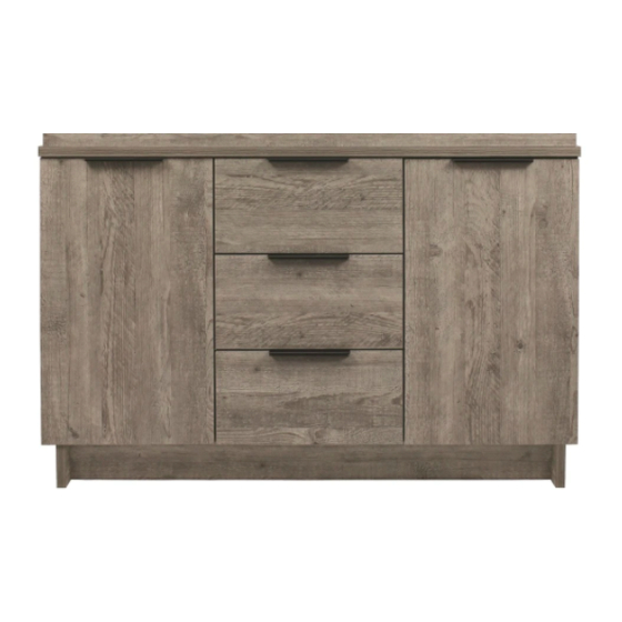
- Page 20 Step 33 Assembly is complete...
Need help?
Do you have a question about the OakStyle Urban 230 and is the answer not in the manual?
Questions and answers