
Related Manuals for Aqua One Inspire 60 Mk2


Summary of Contents for Aqua One Inspire 60 Mk2
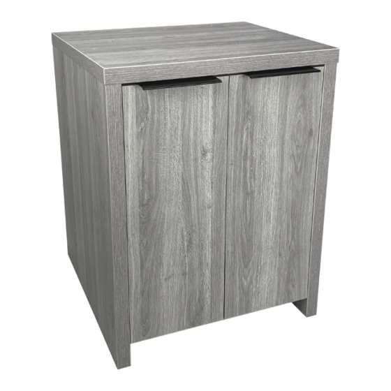
- Page 1 Assembly Instructions Please keep for future reference Inspire 60 Mk2 Version 1 : 21/07/2020 Important - Please read these instructions fully before starting assembly ALR3663...
-
Page 2: Care And Maintenance
Safety and Care Advice Important - Please read these instructions fully before starting assembly • Warning: This unit weighs • Make sure you have enough • We do not approximately 16kgs. space to layout the parts before recommend the Please lift with care. starting. - Page 3 Panels & Fittings Please check you have all the panels and fittings listed below Base (D2941_01) (D2942_01) (598 x 398mm) (524 x 347mm) Left Side Right Side Rail (DF-00021089) (DF-00021090) (D2943_01) (715 x 396mm) (715 x 396mm) (524 x 57mm) Back (D2945_01) (524 x 424mm)
- Page 4 Step 1 Prepare the Left Side Screw 6 Large Metal Dowels into the Left Side. Push 2 Hollow Core Locking Nuts into the Left Side, making sure that they are flush against the panel’s surface. Using a hammer, tap in the pin on the Hollow Core Locking Nut.
- Page 5 Step 3 Prepare the Top Finished front edge Screw 4 Small Metal Dowels into the Top. Step 4 Join the Top to the Left Side Slide the Small Metal Dowels fitted to the Top into the Hollow Core Locking Nuts fitted to the Finished Left Side.
- Page 6 Step 6 Fit the Base to the Left Side Push the Base down onto the Left Side. Use a screwdriver to Finished tighten the 2 Large front edge Locking Nuts fitted to the Base. Turn the Large Locking Nuts as far as they will go - more than 1/2 a turn.
- Page 7 Step 9 Step 9 Fit the 2 Rails Push the 2 Rails down onto the Left Side. Use a screwdriver to tighten the 2 Large Locking Nuts fitted to the Rails. Step 10 Fit the Back Push the Back down onto the Left Side.
- Page 8 Step 11 Fit the Right Side Push the Right Side down onto the assembly. Use a screwdriver to tighten the 6 Large Locking Nuts fitted to the Base, the 2 Rails, and the Back. Insert a screwdriver into the 2 Hollow Core Locking Nuts and turn the nuts inside as far as they will go.
- Page 9 Step 13 Fit the Doors and Handles We recommend that you fit the top Hinge first, then align and fit the other Hinge. Push the Hinge onto the front part of the Hinge Plate. The recess at the bottom of Screw B goes into the slot in the Hinge Plate.
- Page 10 Step 14 Adjust the Doors if required Before adjusting the Doors, use a spirit level to check the Top (or Base) of the unit is level, front-to-back and side-to-side in the 3 positions shown. Use suitable packing pieces (not supplied) to make the unit level BEFORE making any adjustment to the...
- Page 11 Step 15 Attach the Attach the Fit the Overbalance Strap to the wall Strap to the unit Protector Kit Wall Fixing Strap To prevent possible (not supplied) Strap Washer overbalancing we Washer Washer recommend that this unit Screw is secured to a suitable Screw wall by fitting of the (not supplied)
Need help?
Do you have a question about the Inspire 60 Mk2 and is the answer not in the manual?
Questions and answers