
Related Manuals for Sony BKS-R3219A


Summary of Contents for Sony BKS-R3219A
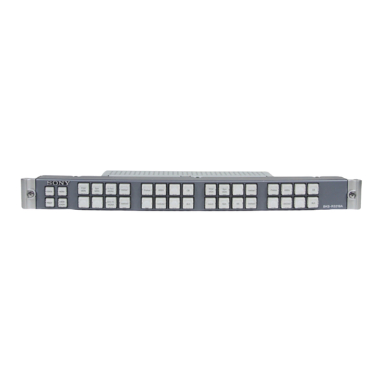
- Page 1 32 BUTTON REMOTE PANEL BKS-R3219A 16 BUTTON LED REMOTE PANEL BKS-R1617A INSTALLATION AND SYSTEM SETUP MANUAL 1st Edition (Revised 1) Serial No. 10001 and Higher: BKS-R3219A Serial No. 10001 and Higher: BKS-R1617A...
- Page 2 électrique, d’incendie ou de blessure n’effectuer que les réparations indiquées dans le mode d’emploi à moins d’être qualifié pour en effectuer d’autres. Pour toute réparation faire appel à une personne compétente uniquement. BKS-R3219A/R1617A I&SSM...
- Page 3 Operation Manual. 6. When performing the installation, keep the following space away from walls in order to obtain proper exhaust and radiation of heat. Rear: 10 cm (4 inches) or more 1 (P) BKS-R3219A/R1617A I&SSM BKS-R3219A/R1617A I&SSM...
-
Page 5: Table Of Contents
2-11. Settings by Using the Buttons (Setup Function) ..... 2-8 6-1. Error Messages ............... 6-1 2-11-1. Setting the Station Number ........2-8 6-2. Data Backup ..............6-2 2-11-2. Setup Operations ........... 2-9 2-11-3. List of Setup Operations ........2-10 BKS-R3219A/R1617A I&SSM... -
Page 7: Manual Structure
This manual describes the detailed information on how to operate this unit. The operation manual is stored as a PDF file in the CD-ROM supplied with the IXS-6600-C/IXS-6700-C. If this manual is required, please contact your local Sony Sales Office/Service Center..Maintenance Manual (Available on request) This manual describes the information that premises the parts level service (parts replacement, parts list, diagrams, etc.). -
Page 9: Overview
It is possible to setup multiple names to describe the terminals, such as “Type + Number” name and “Descrip- tion” name, or “Alias” name. BKS-R3219A/R1617A I&SSM... -
Page 10: Compatibility Between The S-Bus P1 (S-P1) Type And S-Bus P2 (S-P2) Type
1-3. Compatibility between the S-BUS P1 (S-P1) Type and S-BUS P2 (S-P2) Type There are two types of Sony Routing Switcher. One is the “S-BUS P1” type (abbreviated as S-P1 hereaf- ter) that supports the virtual matrix size 512, and the other is the “S-BUS P2” type (abbreviated as S-P2 hereafter) that supports the virtual matrix size 1024. -
Page 11: Constituent Devices Of Routing Switcher System
For the BZR-20 installation procedure, refer to the Installation Manual in the CD-ROM supplied with the IXS-6600/IXS-6700, HKSP-R80 and HDS-X5800 . . Microsoft Excel is installed. . DirectX (V6.1a or higher) is installed. . BZR-2000 (V1.70 or higher) is installed when using GUI for setup. BKS-R3219A/R1617A I&SSM... -
Page 12: Controls By Routing Switcher System
Function : With this, the one-to-one port communication between two units is performed. It is used when a Sony routing switcher is used as a simple matrix switcher when receiving controls from the controller of other manufacturers via RS-422A. RS-232C D-sub 9-pin... -
Page 13: S-Bus Control
1-5-2. S-BUS Control The Sony routing switcher system uses the Sony unique remote control protocol called S-BUS (Sony serial bus) for controlling the switcher system. In the S-BUS control, the multiple routing switchers and remote control panels are connected to a single bus line to form a control network called the S-BUS data link. - Page 14 . In the secondary controller and routing switcher, only one REMOTE 1 connector can be used each. How to use the L-type and Y-type bridges The L-type and Y-type bridges are supplied with the BKS-R1617A/BKS-R3219A. Use the L-type and Y- type bridges as follows.
-
Page 15: Rs-422A Control
1-5-3. RS-422A Control SONY Routing switcher system can be controlled from an external control equipment that is connected to the REMOTE2 (D-sub 9-pin) connector with the RS-422A interface. In addition, the protocol (CART++) can be added so that up to 4093 inputs x 4093 outputs x 8 levels can be controlled. -
Page 16: System Connection Example
*1 : (S) indicates the secondary station. For the secondary stations, set the station ID in the range of ID = 2 to 254 in the manner that the same ID must not be duplicated. *2 : Install the 75 Z terminators to the T-type bridge or Y-type bridge of the last device on the S-BUS data link and to the unused REMOTE 1 connector. BKS-R3219A/R1617A I&SSM... -
Page 17: Remote2 (Rs-422A) Control System Connection Example
: S-BUS : 75 Z terminator : RS-422A : T-type bridge : Standard units making up Sony routing system (P) (S) : The setting of P/S switch on the CPU board. Direct mode connection example RS-422A Controller (Host CPU) -
Page 19: Installation
Setting the On-Board Switches and Switches Description of LEDs Attach the key Label 2-10. Attach the key Label Settings by Using the 2-11. Settings by Using the Buttons (Setup Function) Buttons (Setup Function) Initial setting Settings Operation check Confirmation of Function BKS-R3219A/R1617A I&SSM... -
Page 20: Operating Environment
AC inlet As the inrush current at turn-on is a maximum of 13 A (at 100 V) /47 A (at 240 V) with the BKS-R3219A, or a maximum of 12 A (at 100 V) /40 A (at 240 V) with the BKS-R1617A, the capacity of the AC power must be commensurate with this source load. -
Page 21: Installation Space
2-4. Installation Space The dimensions of the BKS-R3219A and BKS-R1617A are the same. (99) BKS-R3219A BKS-R1617A Unit : mm BKS-R3219A/R1617A I&SSM... -
Page 22: Rack Mounting
2-6. For Use in an OB Van To install the unit into a rack, have the four binding-head When the BKS-R3219A/R1617A is to be used in an OB screws (+B5 x 10) ready. van, be sure to band the cables to a rack strut to avoid Secure the front panel of the unit to the rack with the screws. -
Page 23: Input And Output Signals Of Connectors
Transmitted data (+) Common ground No connection Common ground RX (+) Received data (+) TX (_) Transmitted data (_) Frame ground The Frame ground pin and the Common ground pin are connected each other internally in the BKS machine. BKS-R3219A/R1617A I&SSM... -
Page 24: Setting The On-Board Switches And Description Of Leds
2-9. Setting the On-Board Switches and Description of LEDs The number shown in the parentheses ( ) indicates the address on the circuit board. CPU-420 board (BKS-R3219A/BKS-R1617A) Side A < LED > <Switch > D71 (D-2) : + + + + + 12 V... -
Page 25: Attach The Key Label
3. Cut the paper to the button size as shown on the right. CAM 3 Key label guide . For a large button (13 x 13 mm) _0.2 . For a small button (10 x 10 mm) _0.2 BKS-R3219A/R1617A I&SSM... -
Page 26: How To Attach The Key Label
2 are not required. 4. Install the button in the original location. 3. Press the appropriate source/destination select buttons so that the desired station number is obtained. 4. Press the LOCK (CHOP) button. The set station number is registered. BKS-R3219A/R1617A I&SSM... -
Page 27: Setup Operations
While holding down buttons 1, 2, 3 and 4, turn the power on. Setting 32-source select mode (BKS-R3219A) The station number can be set with binary coding using While holding down buttons 1 and 4, turn the power on. -
Page 28: List Of Setup Operations
Single-use mode 5, 8 Prompt lamp-light mode 1, 3 Status display lamp-light mode 1, 2 , 3 32-source select mode (BKS-R3219A) 1, 4 16-source select mode (BKS-R1617A) 1, 4 (5, 7) 16 source/16 destination select mode 1 5, 6 (BKS-R3219A) -
Page 29: Settings
List of this destination name is called “available destination table”. (This procedure is not needed when there is no need to limit the destination to be controlled, or BPS selection method is used.) It continues to the following page. BKS-R3219A/R1617A I&SSM... - Page 30 Add BKS-R3219A/R1617A to the system Setting of secondary station at BKS-R3219A/R1617A See Section 3-4 for description of setup method. Change Copy the setting from another panel. setting L: COPY TABLE DATA FROM Set the level to control. Set the parent unit setting and child unit setting when multiple control units are to be used.
-
Page 31: Symbols Used In This Manual
Note) In IXS-6600/IXS-6700, “P/S switch on CPU board” means S1203-2 and 3 on the CA-65 board. In HKSP-R80, it means S803-2 and 3 on the CPU-355 board. In HDS-X5800, it means S702-1, 2, 3, and 4 on the CPU-339 board. BKS-R3219A/R1617A I&SSM... - Page 32 Perform the respective setups of Section 3-4 from the secondary station menu screen. When all setups are completed, return to the system status screen. Turn the power of the primary station off and then on again. BKS-R3219A/R1617A I&SSM...
-
Page 33: Display Screens, And Moving Between The Display Screens
Setting screen Setting of the tertiary station *1 : The menu items can be selected in the following two ways. See the “Menu screen” on the next page. *2 : See the “Menu screen/Secondary station” on page 3-7. BKS-R3219A/R1617A I&SSM... - Page 34 System Status Screen SONY INTEGRATED ROUTING SYSTEM IXS-6700 V1.0 ITEM ROM CHECK SUM A43F RAM READ AND WRITE The system status screen appears when the main power of REFERENCE SIGNAL the primary station is turned on. S-BUS LINK TERMINATE REAL TIME CLOCK When [Ctrl] _ [X] are pressed, the menu screen appears.
- Page 35 4 on the secondary station menu screen. Ctrl-D:RETURN When [Ctrl] _ [D] are pressed on the secondary station Secondary station menu screen (BKS-R3219A) menu screen, the display returns to the primary station menu screen. Response of the routing switcher system becomes slower...
-
Page 36: Setting Items Of The Secondary Station
“Type + Number” name can be selected freely. Each time [Ctrl] _ [N] are pressed, the Description name input mode (Crrl-N: DESCRIP. NAME) and “Type + Number” name input mode (Crrl-N: Type + Num) will be switched alternately. BKS-R3219A/R1617A I&SSM... - Page 37 SONY ROUTING SYSTEM SETUP MENU BKS-R1617A V2.23 STATION NUMBER 5 SONY ROUTING SYSTEM SETUP MENU BKS-R3219A V2.23 STATION NUMBER 4 SET PHANTOM TABLE (PHANTOM:DESTINATION<SOURCE-LEVEL) (G.PHANTOM NAME:NUMBER) SET PHANTOM TABLE (PHANTOM:DESTINATION<SOURCE-LEVEL) (G.PHANTOM NAME:NUMBER) PHANTOM | DEST | SOURCE | LEVEL1-8 | PHANTOM | DEST...
- Page 38 Data set at the menu item [SET AVAIL- Output the signal switching request Process nothing ABLE DESTINATION] are copied. The copy function of BKS-R3219A/R1617A guarantees upper compatibility only. To return to the menu screen of the secondary station Press [Ctrl] _ [E].
- Page 39 DEST button lights in green. N: Type+Num”. Be sure to set either source or destination on the respective buttons (keys) when BKS-R3219A. When “Ctrl_ N : Type + Num” is displayed on the If both source and destination are set to the same screen, it means that the name mode will be button (key), it will cause malfunction.
- Page 40 Block 3 Block 4 EJECT, REC, REW, PLAY, F FWD, or STOP functions can be set to any selection button and used to control the SONY ROUTING SYSTEM SETUP MENU BKS-R1617A V2.23 STATION NUMBER 5 VTR from the control panel.
- Page 41 . The blank destination cannot be selected from the panel. To return to the menu screen of the primary station Press [Ctrl] _ [D]. SONY ROUTING SYSTEM SETUP MENU BKS-R3219A V2.23 STATION NUMBER 4 SELECT DESTINATION NAME 0001=OUT001 0002=OUT002 0003=OUT003...
- Page 42 ..Procedure of setting SELECT SOURCE NAME SONY ROUTING SYSTEM SETUP MENU BKS-R3219A V2.23 STATION NUMBER 4 Sets the source terminals that can be selected for a specific SELECT SOURCE NAME SRC TOP -SRC END =DST TOP -DST END destination terminal.
- Page 43 Source name that is actually selected will be displayed by signal and setting items are as following: following the source connected to the route destination when the route setting is performed. SONY ROUTING SYSTEM SETUP MENU BKS-R6010 V1.00 STATION NUMBER 2 SET ROUTE (ROUTE DESTINATION:DESTINATION<SOURCE-LEVEL)
- Page 44 3. Setting of the entered name is confirmed by pressing SONY ROUTING SYSTEM SETUP MENU BKS-R3219A V2.23 STATION NUMBER 2 [Enter]. SET ROUTE(ROUTE DESTINATION:DESTINATION<SOURCE-LEVEL) PAGE = 1 ROUTE | DEST | SOURCE | LEVEL1-8 | ROUTE | DEST | SOURCE | LEVEL1-8 OUT001 : OUT017 <...
- Page 45 Alias name. If you do not want to change the default value, press [Enter] without entering any number. SONY ROUTING SYSTEM SETUP MENU BKS-R3219A V2.23 STATION NUMBER 6 SOURCE SONY ROUTING SYSTEM SETUP MENU BKS-R1617A V2.23...
- Page 46 With BZR-2000, up to seven names other than the descrip- tion name can be assigned to one source. Each of these names is known as an “Alias”. With BKS-R1617A/R3219A, SONY ROUTING SYSTEM SETUP MENU BKS-R3219A V2.23 STATION NUMBER 2 SET PANEL STATUS a set with a description and a custom Alias can be saved.
- Page 47 Up to ten mother-daughter disallow switching from the ON AIR panel. pairs can be set. Models such as BKS-R3216, BKS-R1617A, and BKS-R3219A are used as a daughter panel. NORMAL= Disallow switching during PROTECT.
- Page 48 “MONI” button needs MOTHER STATION ID = 005 (BKS-R3219A) BLOCK & MOTHER STATION LIST to be set on the source button of the “N: SET PANEL BLOCK 1 = STATION 005 | BLOCK 6 = ..
- Page 49 Monitor function has realized this using software. Example of the source offset system HD signal Down-conversion D1signal HD system Monitor display panel Standard system Source offset SOURCE OFFSET setting value 3-21 BKS-R3219A/R1617A I&SSM...
-
Page 51: Confirmation Of Function
This menu takes out only the system status from the memory, and displays the status, corresponding station and time of occurrence. Therefore, the [W] menu is used to check the status and to find the station issuing the error and the time of error occurrence. BKS-R3219A/R1617A I&SSM... -
Page 52: Function Check After Power On
Error message 2007.04.12-15:42 S-BUS LINK DISCONNECTED TO CHANNEL A 2007.04.12-16:28 STARTED BY BKS-R3219A Ver2.23 IN STATION 11 2007.04.12-17:31 STARTED BY BKS-R1617A Ver2.23 IN STATION 32 2007.04.12-18:51 MISSING REFERENCE SIGNAL IN STATION 10 2007.04.12-19:15 POWER SUPPLY UNIT B DOWN IN STATION 4 2007.04.12-20:11 X-POINT ERROR IN STATION 10... -
Page 53: Technical Information
(IN001 to IN004) to the cross-point status of OUT017. At this time, the level of Switcher 1 and that of Switcher 2 must be the same. IN002 IN004 IN001 IN003 OUT001 Switcher 1 IN006 IN008 IN005 IN007 OUT017 Switcher 2 BKS-R3219A/R1617A I&SSM... -
Page 54: Example Of Using Route Function
(OUT001- Fig. 1. IN001/OUT017-IN005) to the remote control, and by executing this phantom. SONY ROUTING SYSTEM SETUP MENU BKS-R3219A V2.23 STATION NUMBER 10 (Cross point for OUT017-IN005 will not execute if the SET ROUTE(ROUTE DESTINATION:DESTINATION<SOURCE-LEVEL) - Page 55 The keys will be assigned on the BKS-R1617A as shown below. EX01 EX02 EX03 EX04 IN06 IN07 IN08 IN01 IN06 OU15 EX001 EX003 IN006 IN008 OUT015 OUT016 EX002 EX004 IN007 Fig. 4 Panel Display (BKS-R1617A) EX001 to EX004 is a local phantom. BKS-R3219A/R1617A I&SSM...
- Page 56 Panel setting is set as following. Predefined cross-point can be switched by selecting EX001 to IN006 when the Control Destination is selected by SONY ROUTING SYSTEM SETUP MENU BKS-R1617A V2.23 STATION NUMBER 10 pressing OUT015 key. IN001 to IN008 will be displayed...
-
Page 57: Relationship With Z: Set Panel Status Setting Items
Fig. 9 Route Multistage Setting Up to 5 stages is possible for route setting as in figure. Deployment of cross-point over 5 stages or displaying of source going over 5 stages for status display will not be done. BKS-R3219A/R1617A I&SSM... -
Page 58: Multiple Terminal Name Function
The BZR-2000 operations can be used to send a different Alias for each operating location to a S-BUS connectable device with a terminal name display function. The following devices can display an Alias. Remote control panel: BKS-R1617, BKS-R3216, BKS-R3220, BKS-R1621, BKS-R3240A, BKS-R3242A, BKS-R3248A, BKS-R3219A, BKS-R1617A, BKS-R6010 BKS-R3219A/R1617A I&SSM... - Page 59 The CSV files can be used by spreadsheet software such as MS-Excel to easily edit the data. Please refer to the Operation Manual for BZR-2000 or Help for detailed information about the multiple terminal name function. BKS-R3219A/R1617A I&SSM...
-
Page 60: Virtual Monitor Function
(Supported HDS- HDS- X5800 X5800 by BKS-R1617/R3219/ R3220 V1.10 or higher.) HDS- HDS- X5800 X5800 Remote panel S-BUS Set OUT544. IN1-IN528 and OUT1-OUT543 can be monitored. BKS-R3219A/R1617A I&SSM... -
Page 61: Configuring The Settings
4. Move the cursor to “CONTROL DESTINATION =” and enter the number of the terminal that you want to assign to the monitoring function. Ex.: Output the result from monitoring on the OUT002 terminal. SONY ROUTING SYSTEM SETUP MENU BKS-R1617A V2.23 STATION NUMBER 2 SET PANEL TABLE(SOURCE) -
Page 63: Service Overview
*1) : The “Com E (Communication Error)” is continuously displayed until the normal communication state is resumed. *2) : When the PHANTOM PROTECT item in the terminal menu “Z: SET PANEL STATUS” is set to “FULL PROT”, the ID may be displayed as “0”. BKS-R3219A/R1617A I&SSM... -
Page 64: Data Backup
Use the software BZR-20 supplied with the primary station to create the backup copy of the system setup data. For the method of creating the backup copy of the system setup data, refer to the Installation Manual of the respec- tive primary stations. BKS-R3219A/R1617A I&SSM... - Page 66 BKS-R3219A (SY) Sony Corporation BKS-R1617A (SY) E 2008. 3 16 9-968-376-02 ©2007...
Need help?
Do you have a question about the BKS-R3219A and is the answer not in the manual?
Questions and answers