
Related Manuals for EXFO EPM-500


Summary of Contents for EXFO EPM-500
- Page 1 POWER METER/LIGHT SOURCE/ OPTICAL LOSS TEST SET EPM-500/ELS-500/EOT-500 NETWORK TESTING USER GUIDE...
- Page 2 Information provided by EXFO is believed to be accurate and reliable. However, no responsibility is assumed by EXFO for its use nor for any infringements of patents or other rights of third parties that may result from its use. No license is granted by implication or otherwise under any patent rights of EXFO.
-
Page 3: Table Of Contents
Accessing and Navigating Setup Menus ............7 Installing the EXFO Universal Interface (EUI) ............. 8 Cleaning and Connecting Optical Fibers ............9 4 Measuring Power or Loss (EPM-500 and EOT-500) ....10 Nulling Electrical Offsets ................. 10 Referencing Your Power Meter to a Source ............. 11 Measuring Power or Loss ................ - Page 4 Reverting Unit to Factory Settings ..............31 Error Codes and Descriptions ................31 Contacting the Technical Support Group ............32 Finding Information on the EXFO Web Site ............ 33 Transportation ....................33 9 Warranty .................. 34 General Information ..................34 Liability ......................
-
Page 5: Certification Information
Canada G1M 2K2 (418) 683-0211 Equipment Type/Environment: Industrial Scientific Equipment Trade Name/Model No.: EPM-500 Power Meter, ELS-500 Light Source, EOT-500 OLTS Standard(s) to which Conformity is Declared: EN 60825-1: 1994/ Safety of Laser Products-Part 1: Equipment Classification, Requirement, and A2: 2001 User’s guide... -
Page 6: Introducing The Epm-500/Els-500/Eot-500
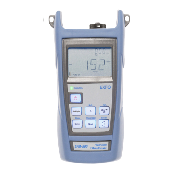
Transmission of wavelength to compatible power meter in automatic wavelength or auto-switching mode Modulated signal emission or detection (270 Hz, 1 kHz and 2 kHz) compatible with other EXFO units Data storage on unit and USB transfer to a computer User-configurable pass/fail thresholds with LED indicator... - Page 7 LCD display Shoulder Keypad strap eyelet (EOT-500 shown) DC connector Stand Power meter Light source detector port ports EPM-500 EOT-500 ELS-500 Visual fault locator port Safety label and serial number (under the stand) USB connector Quick reference labels Battery compartment...
-
Page 8: Power Sources
Introducing the EPM-500/ELS-500/EOT-500 Power Sources The units operate with the following power sources: AC adapter (connected to standard power outlet—indoor use only) Compatible car outlet adapter available upon request. Li-Ion rechargeable battery (automatically takes over if you unplug the AC adapter) MPORTANT If the battery level becomes too low, the unit turns itself off. -
Page 9: Safety Information
Do not view directly with optical instruments. Note: Label shown for information purposes only. It is not affixed to your product. Note: Units without VCSEL sources are Class 1 products. EPM-500/ELS-500/EOT-500... -
Page 10: Laser Safety Information (Units With Vfl)
Safety Information Laser Safety Information (Units with VFL) Your instrument is a Class 3R laser product in compliance with standards IEC 60825-1 Amendment 2: 2001 and 21 CFR 1040.10. It is potentially harmful in direct intrabeam viewing. The following label(s) indicate that the product contains a Class 3R source: If VFL option is available IEC 60825-1:1993+A2:2001 21 CFR 1040.10... -
Page 11: Getting Started
3 Getting Started Turning the Unit On and Off When you turn off the EPM-500 or the EOT-500, it saves the current wavelength, unit and reference power. MPORTANT If you remove batteries (and the AC adapter is unplugged), the unit will turn off without saving the above values. -
Page 12: Activating The Backlight
(one level at a time). Note: Details about each menu option are given in this user guide. EOT-500 Normal Mode DATA CAB 1 PREF *: Default cable name EPM-500 ELS-500 Normal Mode Normal Mode DATA CAB 1 PREF *: Default cable name... -
Page 13: Installing The Exfo Universal Interface (Eui)
Installing the EXFO Universal Interface (EUI) The EUI fixed baseplate is available for connectors with angled (APC) or non-angled (UPC) polishing. A green border around the baseplate indicates that it is for APC-type connectors, as shown below: Green border Bare metal... -
Page 14: Cleaning And Connecting Optical Fibers
To ensure maximum power and to avoid erroneous readings: Always clean fiber ends as explained below before inserting them into the port. EXFO is not responsible for damage or errors caused by bad fiber cleaning or handling. Ensure that your patchcord has appropriate connectors. Joining mismatched connectors will damage the ferrules. -
Page 15: Measuring Power Or Loss (Epm-500 And Eot-500)
4 Measuring Power or Loss (EPM-500 and EOT-500) Nulling Electrical Offsets Temperature and humidity variations affect the performance of electronic circuits and optical detectors. Nulling the electrical offsets eliminates these effects. Your unit has been designed not to require offset nulling under normal operation, but you should perform it whenever environmental conditions change significantly or when measuring very low power values. -
Page 16: Referencing Your Power Meter To A Source
Measuring Power or Loss (EPM-500 and EOT-500) Referencing Your Power Meter to a Source In reference mode, your unit displays the loss created by the fiber under test only, since a reference value is subtracted from the measured power. Note: You must set a reference value separately for each wavelength. -
Page 17: Measuring Power Or Loss
2. Check and clean your fibers appropriately for optimum performance (see Cleaning and Connecting Optical Fibers on page 9). 3. For loss measurements, reference your power meter to a light source (see Referencing Your Power Meter to a Source on page 11), then deactivate the light source. EPM-500/ELS-500/EOT-500... - Page 18 Measuring Power or Loss (EPM-500 and EOT-500) 4. Using the proper adapter and test jumpers, connect a fiber under test to a light source (such as ELS-500 or EOT-500) and to the detector port of your unit. Note: If you have referenced your power meter to a source, simply connect a fiber under test to the test jumpers used for referencing.
-
Page 19: Automatically Detecting Wavelength
ELS-500: see Modulating the Source Signal on page 17) or in auto-switching mode (see Using Auto-Switching Mode on page 17). Your power meter automatically matches the source wavelength. If the wavelengths differ, it also beeps and returns you to normal operating mode. EPM-500/ELS-500/EOT-500... -
Page 20: Setting Pass/Fail Thresholds
Measuring Power or Loss (EPM-500 and EOT-500) Setting Pass/Fail Thresholds You can define thresholds to specify acceptable power (dBm) or loss (dB) values for each wavelength. Thresholds are often supplied by system manufacturers and depend on the system deployed. When a threshold is activated, the PASS/FAIL LED is turned on. -
Page 21: Using A Light Source (Els-500 And Eot-500) Or Vfl
(two-port models). The EOT-500 may contain up to three sources. Note: The VFL option may also be present on the EPM-500. Activating/Deactivating a Light Source or VFL Only one source may be active at a time. When no source is active, the unit displays OFF. -
Page 22: Modulating The Source Signal
Using a Light Source (ELS-500 and EOT-500) or VFL Modulating the Source Signal When you activate the first source (after turning on the unit), the signal is always CW (unmodulated). When you switch sources, the modulation remains the same (VFL remembers its own modulation). Modulation is indicated in the top left (port #1) or top right (port #2) corner. -
Page 23: Sending Source Power Value With Signal
Your source can transmit a user-defined power value to compatible power meters (such as EOT-500 and EPM-500) through the fiber. If the reference source is far from the power meter, you can connect your source to the power meter to send the reference value. - Page 24 Using a Light Source (ELS-500 and EOT-500) or VFL To use the actual source output power as reference (EOT-500 only): 1. Connect a fiber between the source and power meter of same unit. 2. Activate the source at the desired wavelength. 3.
-
Page 25: Saving And Recalling Power/Loss Values
5. While a digit blinks, hold down a few seconds to save the modified value (it remains in memory even when you turn off the unit) or press to return to the previous value without saving. 6. Press twice to exit setup menus. EPM-500/ELS-500/EOT-500... -
Page 26: Saving, Recalling And Deleting Data
Saving and Recalling Power/Loss Values Saving, Recalling and Deleting Data MPORTANT You cannot recover deleted data. Ensure that you transfer your data to a computer if you intend to use it later. Deleting a single value does not free memory. To free memory, you must delete all data at once. - Page 27 Recall indicator is displayed with the last cable name, then the last saved value and its fiber ID. 2. When fiber ID is displayed, hold down both a few seconds. The unit displays “dEL” and “ALL”, then automatically returns to normal mode. EPM-500/ELS-500/EOT-500...
-
Page 28: Transferring Data To A Computer
Saving and Recalling Power/Loss Values Transferring Data to a Computer Using an appropriate USB cable and the Handheld Data Transfer software, you can transfer saved data from your handheld unit to a computer. This way, you can increase storage capacity, perform better analyses on your data and create reports. MPORTANT Transferred data is not automatically deleted from your unit. -
Page 29: Maintenance
If any liquids are spilled on or into the unit, turn off the power immediately and let the unit dry completely. ARNING Use of controls, adjustments and procedures for operation and maintenance other than those specified herein may result in hazardous radiation exposure. EPM-500/ELS-500/EOT-500... -
Page 30: Cleaning Eui Connectors
Pull Push 2. Moisten a 2.5 mm cleaning tip provided by EXFO with one drop of isopropyl alcohol (alcohol may leave traces if used abundantly). 3. Slowly insert the cleaning tip into the EUI adapter until it comes out on the other side (a slow clockwise rotating movement may help). - Page 31 6c. With a dry lint-free wiping cloth, gently wipe the same surfaces to ensure that the connector and ferrule are perfectly dry. 6d. Verify connector surface with a portable fiber-optic microscope (e.g., EXFO’s FOMS) or fiber inspection probe (e.g., EXFO’s FIP). ARNING Verifying the surface of the connector WHILE THE UNIT IS ACTIVE WILL result in permanent eye damage.
-
Page 32: Cleaning Detector Ports
Maintenance Cleaning Detector Ports Regular cleaning of detectors will help maintain measurement accuracy. MPORTANT Always cover detectors with protective caps when unit is not in use. To clean detector ports: 1. Remove the protective cap and adapter (FOA) from the detector. 2. -
Page 33: Replacing Battery
The FlexCare warranty program includes Calibration/Verification packages (see Service and Repairs on page 38). To view the last calibration date (EOT-500 and EPM-500 only): 1. From normal operating mode, hold down for a few seconds. The unit displays the first embedded software version. -
Page 34: Recycling And Disposal (Applies To European Union Only)
European Union member state with legislation regarding Directive 2002/96/EC. Except for reasons of safety or environmental benefit, equipment manufactured by EXFO, under its brand name, is generally designed to facilitate dismantling and reclamation. For complete recycling/disposal procedures and contact information, visit the EXFO... -
Page 35: Troubleshooting
Changed unit or reference value are replaced by other values after a while. Many beeps, unstable optical Power too low to Increase source power power and blinking Auto (or recognize Auto mode or switch source to modulation) indicator. (or modulation). EPM-500/ELS-500/EOT-500... -
Page 36: Reverting Unit To Factory Settings
Add data. You pressed Recall but no data was saved. Last saved data deleted. All data deleted. 29/30/ Calibration errors. Contact EXFO. 34/36/ 56/57 18/52 Incompatible wavelengths or Match source and power meter power too low in PREF on EOT-500. -
Page 37: Contacting The Technical Support Group
Contacting the Technical Support Group To obtain after-sales service or technical support for this product, contact EXFO at one of the following numbers. The Technical Support Group is available to take your calls from Monday to Friday, 7:30 a.m. to 8:00 p.m. (Eastern Time in North America). -
Page 38: Finding Information On The Exfo Web Site
3. Click on FAQs and follow the on-screen instructions. You will be given a list of questions pertaining to your subject. The EXFO Web site also provides the product’s most recent technical specifications. Transportation Maintain a temperature range within specifications when transporting the unit. -
Page 39: Warranty
DAMAGES. Liability EXFO shall not be liable for damages resulting from the use of the product, nor shall be responsible for any failure in the performance of other items to which the product is connected or the operation of any system of which the product may be a part. -
Page 40: Exclusions
Warranty Exclusions EXFO reserves the right to make changes in the design or construction of any of its products at any time without incurring obligation to make any changes whatsoever on units purchased. Accessories, including but not limited to fuses, pilot lamps, batteries and universal interfaces (EUI) used with EXFO products are not covered by this warranty. -
Page 41: Service And Repairs
After repair, the equipment will be returned with a repair report. If the equipment is not under warranty, you will be invoiced for the cost appearing on this report. EXFO will pay return-to-customer shipping costs for equipment under warranty. Shipping insurance is at your expense. -
Page 42: Exfo Service Centers Worldwide
Warranty EXFO Service Centers Worldwide If your product requires servicing, contact your nearest authorized service center. EXFO Headquarters Service Center 400 Godin Avenue 1 866 683-0155 (USA and Canada) Vanier (Quebec) G1M 2K2 Tel.: 1 418 683-5498 CANADA Fax: 1 418 683-9224 quebec.service@exfo.com... -
Page 43: A Technical Specifications
MPORTANT The following technical specifications can change without notice. The information presented in this section is provided as a reference only. To obtain this product’s most recent technical specifications, visit the EXFO Web site at www.exfo.com. EPM-500 Specifications Model EPM-502... - Page 44 Technical Specifications EOT-500 Specifications Model EOT-502 EOT-502X GENERAL SPECIFICATIONS Detector Size (H x W x D) 19.0 cm x 10.0 cm x 6.2 cm in x 4 in x 2 10 to −70 26 to −55 Power range (dBm) Weight 0.48 kg (1.1 lb) Wavelength range (nm)
- Page 45 400 Godin Avenue Vanier (Quebec) G1M 2K2 CANADA HEADQUARTERS Tel.: 1 418 683-0211 · Fax: 1 418 683-2170 EXFO AMERICA 4275 Kellway Circle, Suite 122 Addison TX, 75001 USA Tel.: 1 972 836-0100 · Fax: 1 972 836-0164 EXFO EUROPE Le Dynasteur 92366 Meudon la Forêt Cedex FRANCE...
Need help?
Do you have a question about the EPM-500 and is the answer not in the manual?
Questions and answers