
Related Manuals for KYORITSU 3131A


Summary of Contents for KYORITSU 3131A
- Page 1 INSTRUCTION MANUAL ANALOGUE INSULATION TESTER MODEL 3 1 3 1A KYORITSU ELECTRICAL INSTRUMENTS WORKS, LTD., TOKYO JAPAN...
-
Page 2: Table Of Contents
Contents 1. Safety Precautions ................1 2. Features ....................3 3. Specifications ..................4 4. Instrument Layout ................. 6 5. Preparation for Testing ................. 7 5-1 Removing the Cover ..............7 5-2 Mechanical Zero Adjustment ............8 5-3 Battery Voltage Check .............. -
Page 3: Safety Precautions
● The instrument must only be used by a competent trained person and operated in strict accordance with the instructions. KYORITSU will not accept any liability for any damage or injury caused by misuse or non- compliance with the instructions or safety procedures. - Page 4 ● Do not install substitute parts or perform any unauthorized modification of the instrument. Return the instrument to Kyoritsu or your distributor for service and repair to ensure the safety features are maintained. ● Do not replace batteries when the surface of the instrument is wet.
-
Page 5: Features
2. Features MODEL-3131A is an analogue insulation tester with five ranges for insulation resistance measurement and continuity testing (resistance tests) of low voltage installations. ● Designed to safety standards: IEC 61557-1(General requirements for measuring equipment for low voltage distribution systems) -
Page 6: Specifications
3. Specifications ● Measuring Range and Accuracy (at 23±5° C, relative humidity 45-75%) Insulation Resistance Ranges:(IEC 61557-2) Nominal Output Voltage 250V 500V 1000V Measuring Ranges 0 - 100MΩ 0 - 200MΩ 0 - 400MΩ Open-Circuit 250V DC +20% max. 500V DC +20% max. 1000V DC + 20% max. - Page 7 Typical Number of Measurements (central tendency for supply voltage up to 6.5V) Insulation Resistance Ranges: 1000V/400MΩ Range Approx. 500 times min. 500V/200MΩRange Approx. 1300 times min. 250V/100MΩ Range Approx. 1800 times min. Continuity Test (Resistance Test) Ranges: xΩ Range/ x 10Ω Range Approx.
-
Page 8: Instrument Layout
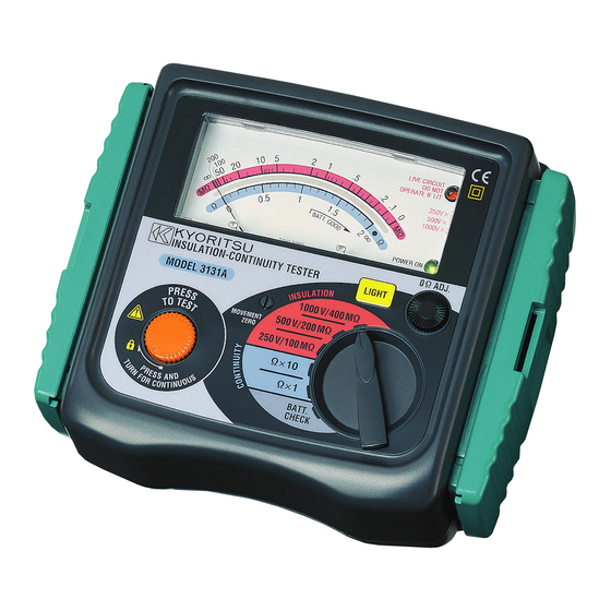
4. Instrument Layout ⑬ ⑫ ⑪ ③ ④ ⑨ ⑩ ⑤ ⑥ ⑦ ① ⑧ ② Fig.1 Part names ①METER MOVEMENT ZERO ADJUST ②TEST BUTTON ③SCALE PLATE ④LIVE CIRCUIT WARNING LED ⑤POWER-ON INDICATION LED ⑥CONTINUITY ZERO ADJUST ⑦LIGHT SWITCH ⑧RANGE SELECTOR SWITCH ⑨TEST PROBE (RED) LINE PROBE ⑩TEST PROBE (BLACK) EARTH PROBE ⑪TEST PROBE CAP (RED) -
Page 9: Preparation For Testing
5. Preparation for Testing 5-1 Removing the Cover Model 3131A has a dedicated cover to protect against an impact from the outside and prevent the operation part, and the connector socket from becoming dirty. Remove the cover and put it on the back side of the main body to make measurements. -
Page 10: Mechanical Zero Adjustment
5-2 Mechanical Zero Adjustment Check that the pointer lines up with the middle of the mark on the scale correctly. If not, adjust it by rotating the meter movement zero adjust with a screwdriver, etc. 5-3 Battery Voltage Check ① Set the range selector switch to BATT. CHECK position. ②... -
Page 11: Operation
6. Operation 6-1 Disconnection and check of power source of circuit under test DANGER ● To avoid possible electrical shock, do not perform measurements on energized (LIVE) circuits. ● Never make measurements with the battery compartment cover removed. CAUTION ● Never press the test button if the live circuit warning LED is lit or the warning buzzer sounds. -
Page 12: Insulation Resistance Measurement
6-2 Insulation Resistance Measurement DANGER ● Always test the circuit or equipment to ensure it is surely de-energized before measurement according to the instruction of 6-1. ● To avoid electrical shock, measurements must be performed on de- energized circuits only. ●... -
Page 13: Continuity Testing (Resistance Tests)
DANGER Do not touch the circuit under test immediately after testing. Capacitance stored in the circuit may cause electric shock. Leave the test probe connected to the circuit and never touch the circuit until the discharge is completed. Principle of Insulation Resistance Measurement Resistance value can be obtained by applying a certain high voltage to the resistance (insulation resistance) and measuring the flowing current. -
Page 14: Continuous Measurement
① Set the range selector switch to the desired position xΩor x 10Ω. ② Short the line probe (red) and the earth clip of the test probe (black) and press the test button. Adjust the ohm zero adjust to zero the pointer on the scale. -
Page 15: Back Light Function
7. Back Light Function To facilitate working at night or dimly lit situations, a back light function is provided which illuminates the display. To operate this function, the back light button must be pressed and released while pressing the test button. The back light continues illuminating for approx. -
Page 16: Battery & Fuse Replacement
8. Battery & Fuse Replacement DANGER ● Never open the battery compartment cover while making measurement. To avoid possible electrical shock, disconnect the test probe before opening the cover for battery and fuse replacement. ● Replacement fuse must have the following rating. Fast acting type, F500mA/600V, φ6.35×32mm 8-1 Battery Replacement ①... -
Page 17: Notes On Accessories
9. Notes on Accessories 9-1 How to Fit Strap Belt and Test Probe Pouch By hanging the instrument around the neck, both hands can be used freely for easy and safety working. ① How to fit the strap belt Fig.9 How to fit the strap belt ②... -
Page 18: Cleaning Of The Instrument
10. Cleaning of the Instrument ◎ Cleaning the meter cover This instrument is managed by our company's quality standard and is delivered in the best condition after passed the inspection. But in the dry time of winter static electricity sometimes builds up on the meter cover due to the characteristic of plastic. - Page 19 MEMO ― 17 ―...
- Page 20 DISTRIBUTOR 92-1487A 01-12 Kyoritsu reserves the rights to change specifications or designs Described in this manual without notice and without obligations. KYORITSU ELECTRICAL INSTRUMENTS WORKS, LTD. No.5-20, Nakane 2― chome, Meguro-ku, Tokyo, 152-0031 Japan Phone: (03) 3723― 0131 Fax: (03) 3723― 0152 URL:http://www.kew-ltd.co.jp...
Need help?
Do you have a question about the 3131A and is the answer not in the manual?
Questions and answers