Table of Contents

Subscribe to Our Youtube Channel
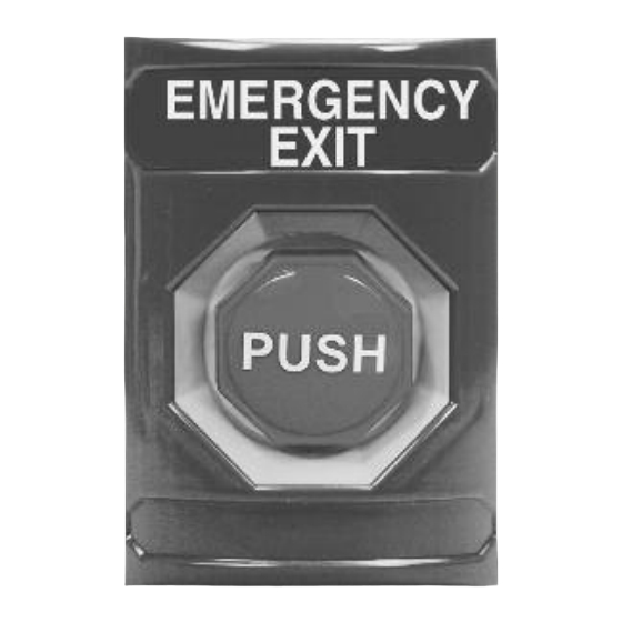
Related Manuals for STI Stopper Station Series


Summary of Contents for STI Stopper Station Series
- Page 1 ompliant STOPPER ® STATION SERIES SS-2008 PUSH BUTTON PNEUMATIC TIMER BUTTON Pneumatic Timer Model SS-2008 ALL MODELS COME WITH A SS-2108 Green COLOR MATCHED SURFACE MOUNT BACKBOX SS-2208 Yellow SS-2308 White SS-2408 Blue...
- Page 2 This push button has been tested according to UL38 and UL2017. Manual fire alarm stations are listed in UL category UNIU and non-fire alarm initiating devices are listed in UL category UEHX. It is important to read, understand and follow all instructions provided with this product.
- Page 3 I. GENERAL Product Dimensions See page 3 Contact Rating One set NO and one set NC Rated at 10 AMP @ 240 VAC Recognized component listing is 1,000,000 cycles II. CONTENTS LIST QTY. DESCRIPTION Push Button Housing Assembly 19001 Allen Head Screw #8-32 x 3/8 in. 19015 Allen Wrench 3/32 in.
- Page 4 PRODUCT DIMENSIONS 1.62 in. 1.5 in. (41mm) 3.25 (82mm) (38mm) 1.375 in. (35mm) VIEW SHOWING FRONT HOUSING REMOVAL BUTTON AND SWITCH ASSEMBLY 10271 SWITCH HOUSING RED, GREEN, YELLOW, 19011 SCREW ALLEN HEAD WHITE AND BLUE #8 - 32 x 3/8 (1) PROVIDED 19015 WRENCH (1) PROVIDED - 3 -...
- Page 5 BACKBOX PREPARATION (NOT INCLUDED WITH FLUSH MOUNT COVERS) .75 in. 1.5 in. (19mm) (38mm) FIELD DRILLING FOR CONDUIT ENTRY IS REQUIRED. LOCATIONS SHOWN ALSO APPLY TO OPPOSITE, 2.375 in. PARALLEL SIDES. (60mm) .75 in. (19mm) BOX MUST BE INSTALLED WITH "TOP"...
- Page 6 CONTACT DIAGRAM INSTALLATION NOTE: NC (GREEN) (BLACK) NC ADA mounting compliance requires the NO (WHITE) operable part of the initiating device (RED) NO shall not be less than 1.1m LEAD WIRE COLORS (3 1/2 ft.) or greater than 1.37m IN PARENTHESIS. (4 1/2 ft.) above finished floor service.
- Page 7 INSTALLATION 19018 ANCHOR (4) PROVIDED IF WIRE ACCESS OR CONDUIT ENTRY HOLES ARE NEEDED, THESE HOLES MUST BE FIELD DRILLED AS REQUIRED. 71100A SURFACE BOX RED, GREEN, YELLOW, WHITE AND BLUE 19014 SCREW #8 X 1 (4) PROVIDED 19021 GROUND LUG (2) PROVIDED PNEUMATIC TIMER DRILL (4)
- Page 8 Unit 49G Pipers Road • Park Farm Industrial Estate • Redditch Worcestershire • B98 0HU • England • Tel: 44 (0) 1527 520 999 Fax: 44 (0) 1527 501 999 • Freephone: 0800 085 1678 (UK only) E-mail: info@sti-europe.com • Web: www.sti-europe.com 2008 A-IS 02/04...
Need help?
Do you have a question about the Stopper Station Series and is the answer not in the manual?
Questions and answers