Advertisement
Quick Links
Safety,
Technology
& Innovation
MF Series
Operating Instructions for MF-2 Safety Switches
CAUTION
This information is designed to help suitably qualified
personnel install and operate STI Safety Switch equipment.
Before using this product, read this guide thoroughly along
with any relevant European and/or National standards e.g.
Machinery Directive 89/392/EEC and it's amendments,
Provision and Use of Work Equipment Regulations.
Further information can be obtained from
KEEP THIS GUIDE FOR FUTURE REFERENCE
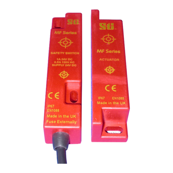
Description
The MF Series safety switches are electronically operated
non-contact safety switch for use in machine guarding
applications.
The non-contact operation makes the MF-2 easy to install
and tolerant to misalignment, providing a simple reliable
solution to machine guard interlocking.
The electronic operation provides additional security and
single point switching. This leads to a more reliable and
secure long term safety solution.
The switch and actuator are IP67 rated and can be used in
wet or dusty environments.
Operation
The MF-2 is designed for use with 'low inrush current' safety
relays like the OMRON SR 131A and SR 231A. Maximum
switching for long life performance is 500mA.
When installed on a machine guard, power is applied, and
the switch and actuator are within the specified operating
range (See table on page 4 for switching distances). The
Normally Closed Contact will be closed and the Normally
Open Contact will be open. The dual color LED will be
GREEN. When the actuator moves out of the operating
range, the Normally Closed Contact will open the Normally
Open Contact will close. The dual color LED will be RED.
The MF-2 safety switch and actuator have a 10mm switching
distance and can approach each other from most angles.
When the switch is closed the targets on the printed face of
the switch must be aligned. To Assure proper operation of
the switch a minimum distance or gap of 2mm must be
maintained between the Switch and actuator. See
Mounting Section for details.
Applications
Interlocked guards where additional security required.
Door locking is not required.
Food and Beverage packing/filling systems
Diary Pharmaceutical Paper Industry
Can Forming and Filling, (Aluminum, Steel, Plastic)
Semiconductor Manufacture/Assembly.
STI
Pending
Approvals
CE
Complies with the relevant sections of the CE
marking directive.
UL
Pending
EUROPEAN DIRECTIVES
Machinery Directive 98/37/EC
Low Voltage Directive 73/23/EC
Electromagnetic Compatibility Directive 89/336/EC
EUROPEAN STANDARDS
EN292
Safety of Machinery
Basic concepts, general principles for design.
EN 60204 Safety of Machinery
Electrical equipment of machines.
EN 954-1
Safety of Machinery
Safety related parts of controls systems
EN 1088
Interlocking devices associated with guards.
EN
Safety of Machinery
60947-5-3
Specification for low voltage switchgear and
control gear.
Declaration of Conformity
A Declaration of Conformity can be obtained from the
OMRON STI Web Site: WWW.STI.COM
Rev. 3.09
MF-2
Advertisement

Subscribe to Our Youtube Channel
Related Manuals for STI MF Series


Summary of Contents for STI MF Series
- Page 1 Provision and Use of Work Equipment Regulations. Further information can be obtained from KEEP THIS GUIDE FOR FUTURE REFERENCE Description The MF Series safety switches are electronically operated non-contact safety switch for use in machine guarding applications. The non-contact operation makes the MF-2 easy to install and tolerant to misalignment, providing a simple reliable solution to machine guard interlocking.
- Page 2 DIMENSIONS Dimensions in MM [Inches] MOUNTING The MF-2 safety switches can approach each other from most angles. When the guard is closed the targets on the printed face of the switch and actuator must be aligned. IMPORTANT: a minimum distance or gap of 2mm must be maintained between the switch and actuator to assure proper switch actuation.
-
Page 3: Operation
The safety relay should require 1 x N/C + 1 x N/O input with a low inrush current input switching circuit. Examples of this type of relay are listed below OMRON STI SR131A / SR231A (See diagram below) SAFETY RELAY... -
Page 4: Technical Specification
Cable length Maximum 100m Construction RED ABS Resin Filled Note The safety contacts of the STI switches are described as normally closed (N/C) i.e. With the guard closed, actuator in place, and the machine able to be started. Specification Changes In the interest of product development, specifications are subject to change without notice. - Page 5 OMRON AUTOMATION AND SAFETY • THE AMERICAS HEADQUARTERS • Chicago, IL USA • 847.843.7900 • 800.556.6766 • www.omron247.com OMRON CANADA, INC. • HEAD OFFICE OMRON ARGENTINA • SALES OFFICE Toronto, ON, Canada • 416.286.6465 • 866.986.6766 • www.omron247.com Cono Sur • 54.11.4783.5300 OMRON ELECTRONICS DE MEXICO •...
Need help?
Do you have a question about the MF Series and is the answer not in the manual?
Questions and answers