Table of Contents

Related Manuals for STI Stopper Station Series


Summary of Contents for STI Stopper Station Series
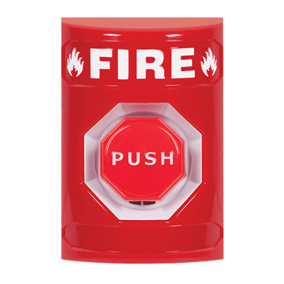
- Page 1 Stopper Station Series SS2xx8 ® Push Button Pneumatic Timer Button for operation Pneumatic Timer Models SS20x8 ALL MODELS COME SS21x8 Green WITH A COLOR SS22x8 Yellow MATCHED SURFACE SS23x8 White MOUNT BACKBOX SS24x8 Blue We protect the things that protect you. ®...
- Page 2 Installation and Service Instructions STOPPER STATION SERIES SS2xx8 ® PUSH BUTTON PNEUMATIC TIMER SAFETY NOTICE TO INSTALLERS AND USERS I. GENERAL Product Dimensions See page 3 Contact Rating One set NO and one set NC Rated at 10 AMP @ 240 VAC Recognized component listing is 1,000,000 cycles UL File #UL57255 Operating Temperature of button 15°-120°F (-9°to +49°C)
- Page 3 Push buttons for outdoor use must be mounted with STI outdoor rated covers. * For access control installations, power for the SS2xx8 must be supplied by a power source Listed to UL294.
- Page 4 6 DIA. HOLES PRODUCT DIMENSIONS JUMPER WIRE NOT PROVIDED 1.62 in. 1.58 in. (41mm) (40mm) 3.25 in. (82mm) BUTTON AND SWITCH ASSEMBLY 19068 SCREW SELF TAPPING (4) PROVIDED 4.87 in. PUSH (124mm) 1.375 in. (35mm) VIEW SHOWING FRONT HOUSING REMOVAL PRODUCT DIMENSIONS BUTTON AND SWITCH ASSEMBLY PART DESCRIPTION...
- Page 5 BUTTON AND SWITCH ASSEMBLY BACKBOX PREPARATION (NOT INCLUDED WITH FLUSH MOUNT COVERS) DRILL POINT LOCATIONS PROVIDED TOP AND BOTTOM FOR 1/2 in. CONDUIT FITTINGS. DRILL AS NEEDED 10271 SWITCH HOUSING RED, GREEN, YELLOW, WHITE AND BLUE FIELD DRILLING FOR CONDUIT ENTRY IS REQUIRED.
- Page 6 CONTACT DIAGRAM BUTTON AND SWITCH ASS NC (GREEN) (BLACK) NC PENS NO (WHITE) (RED) NO ELAY. RATE ACTS LEAD WIRE COLORS IONS BODY IN PARENTHESIS. ANGE NC (GREEN) (BLACK) NC NO (WHITE) (RED) NO CONTACTS One set NO and one set NC FAST SLOW TIMER RANGE ADJUSTMENT SCREW...
- Page 7 INSTALLATION WITH PROVIDED SURFACE BACK BOX ANCHOR (4) PROVIDED KIT-71100A-COLOR SURFACE BOX DRILL (4) 3/16 in. SCREW #6 x 1-1/4 in. DIA HOLES (4) PROVIDED SCREW #6-32 x 1 in. (2) PROVIDED GROUND SCREW BUTTON AND SWITCH ASSEMBLY WITHOUT PROVIDED SURFACE BACK BOX TYPICAL FLUSH MOUNT ADA mounting compliance...
- Page 8 Phone: 248-673-9898 • info@sti-usa.com • www.sti-usa.com Taylor House • 34 Sherwood Road • Bromsgrove, Worcestershire • B60 3DR • England Tel: +44 (0)1527 520 999 • info@sti-emea.com • www.sti-emea.com Unit 7A • Lockhead Avenue • Airport Business Park • Waterford • X91 HWF2 • Ireland info@sti-emea.com •...
Need help?
Do you have a question about the Stopper Station Series and is the answer not in the manual?
Questions and answers