Campbell KH20 Product Manual
Krypton hygrometer
Hide thumbs
Also See for KH20:
- User manual (22 pages) ,
- Instruction manual (20 pages) ,
- Instruction manual (60 pages)

Related Manuals for Campbell KH20


Summary of Contents for Campbell KH20
- Page 1 KH20 Krypton Hygrometer Revision: 05/2020 Copyright © 2010 – 2020 Campbell Scientific, Inc.
-
Page 2: Table Of Contents
KH20 Calibration ................7 7. Maintenance and Calibration ........7 Visual Inspection ..................8 Testing the Source Tube ...............8 Testing the Detector Tube ..............8 Managing the Scaling of KH20 ............8 Calibration ....................9 Appendices A. Calibrating KH20 ............ A-1 Basic Measurement Theory ............. A-1 Calibration of KH20 ................ - Page 3 Wire Color, Function, and Data Logger Connection......6 6-2. KH20 Calibration Ranges ..............7 A-1. Linear Regression Results for KH20 ln(mV) vs. Vapor Density ..A-2 A-2. Final Calibration Values for KH20 ..........A-3 C-1. Default Wiring for Required Sensors ..........C-3 C-2.
- Page 4 Table of Contents C-4. Default Wiring for GPS Receiver ............ C-5 C-5. Default Wiring for Radiation Measurement Option 1 ...... C-5 C-6. Default Wiring for Radiation Measurements Option 2 ....C-6 C-7. A21REL-12 Wiring ................C-8 C-8. CNF4 Wiring ..................C-8 C-9.
-
Page 5: Introduction
Section 3.1, Components (p. 1) Components The KH20 sensor consist of a sensor head with 2 m (6 ft) cables and an electronics box. The following are also shipped with the KH20: • KH20CBL-L25 Power/Signal cable with 8 m (25 ft) length. If a longer cable is desired, order a KH20CBL-L replacement cable and specify the desired length after -L (for example KH20CBL-L50). -
Page 6: Specifications
KH20 is not suitable for absolute water vapor concentration measurements due to its signal offset drift. The KH20 heads are sealed and will not suffer damage should they get wet. In addition, the electronics box and the connectors are housed inside a rain shield that protects them from moisture. -
Page 7: Installation
Shipping: 9.2 kg (20.15 lb) Installation Siting When installing the KH20 sensor for latent heat flux measurement in an eddy- covariance application, proper siting, sensor height, sensor orientation and fetch are important. Mounting 6.2.1 Parts and Tools Needed for Mounting... -
Page 8: Mounting The Electronics Box
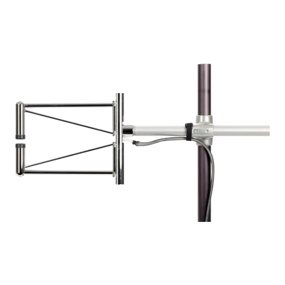
KH20 Krypton Hygrometer FIGURE 6-1. Mounting KH20 to a tripod. 6.2.3 Mounting the Electronics Box Mount the electronics box as follows: Remove the front cover of the rain shield by loosening the two pan-head screws on the bottom front of the rain shield, and then pushing the cover all the way up, and sliding it out. -
Page 9: Proper Mounting Position Of The Electronics Box
Mount the rain shield onto the tripod or tower mast using the U-bolt provided. Make sure that the distance between the KH20 sensor head and the rain shield is within 5 feet so that the cables from the sensor head will be within reach of the electronics box. -
Page 10: Wiring
KH20 Krypton Hygrometer 4. Connect the three cables to the bottom of the electronics box around the U-bolt on the rain shield (see FIGURE 6-3). If there is not enough room for the connectors around the U-bolt, make sure the electronics box is mounted at a highest possible position (see step 2). -
Page 11: Data Logger Programming
KH20 Krypton Hygrometer Data Logger Programming The KH20 sensor outputs 0 to 5 VDC analog signal. These signals can be measured using the VoltDiff instruction on the CRBasic data loggers. Programming basics for CRBasic data loggers are in the following sections. -
Page 12: Visual Inspection
(p. 8) Testing the Detector Tube If the source tube tests fine but the output from KH20 is still in question, perform the following test. Prepare a piece of paper and insert it between the source tube and the detector tube to completely block the optical path. You should see an immediate decrease in the voltage reading, and it should go close to zero. -
Page 13: Calibration
Calibration For quality assurance of the measured data, Campbell Scientific recommends the KH20 be recalibrated every two years. Calibrations require a returned material authorization (RMA) and completion of the “Declaration of Hazardous Material and Decontamination” form. Refer to the... -
Page 14: Calibrating Kh20
ρ. The KH20 sensor uses the UV light emitted by the krypton lamp: major line at 123.58 nm and the minor line at 116.49. - Page 15 ρ . Campbell Scientific performs the calibration twice for each KH20: once with the window cleaned, and again with the window scaled. We then break up the vapor density range into dry and...
- Page 16 Appendix A. Calibrating KH20 TABLE A-2. Final Calibration Values for KH20 Vapor Range Slope Y Intercept Coefficient (g/m ln (V Full Range 1.74 ~ 19.25 -0.205 3087 -0.144 Dry Range 1.74 ~ 9.20 -0.216 3259 -0.151 Wet Range 7.95 ~ 19.25 -0.201...
-
Page 17: Example Program
'CR3000 Series Data Logger 'This data logger program measures KH20 Krypton Hygrometer. 'The station operator must enter the constant and the calibration value for the KH20. 'Search for the text string "unique" to find the locations of these constants 'and enter the appropriate values found from the calibration sheet of the KH20. - Page 18 DataTable (ts_data,True,-1) DataInterval (0,SCAN_INTERVAL,mSec,100) Sample (1,kh_mV,IEEE4) EndTable '*** Program *** BeginProg Scan (SCAN_INTERVAL,mSec,3,0) 'data logger panel temperature. PanelTemp (panel_temp,250) 'Measure battery voltage. Battery (batt_volt) 'Measure KH20. VoltDiff (kh_mV,1,mV5000,1,TRUE,200,250,1,0) ln_kh = LOG(kh_mV) rho_w = ln_kh/xkw CallTable stats CallTable ts_data NextScan EndProg...
-
Page 19: Easyflux ® Dl Cr6Kh20
EasyFlux ® DL CR6KH20 is a CRBasic program that enables a CR6 data logger, along with a KH20 and CSAT3B, to collect fully corrected fluxes of latent heat (H O), sensible heat, and momentum. The program processes the EC data using commonly used corrections in the scientific literature. The program can also calculate the ground surface heat flux and energy closure by adding an optional suite of energy balance sensors. -
Page 20: Precautions
C-13 present the wiring schemes. A KH20 and CSAT3B are the only required sensors for the program. The additional sensors described in the following tables are optional, although the CS106 and FW3 are recommended. Many of the optional sensors are wired to a VOLT116 (or CDM-A116) module, which effectively increases the CR6 analog terminals. -
Page 21: Required Sensors
Appendix C. EasyFlux ® DL CR6KH20 C.3.1 Required Sensors A KH20, CSAT3B, and Temp/RH Probe must be wired to the CR6 for EasyFlux DL CR6KH20 to be functional. TABLE shows the default wiring for these sensors. TABLE C-1. Default Wiring for Required Sensors... -
Page 22: Barometer
Appendix C. EasyFlux ® DL CR6KH20 Once connected, a list of settings is shown. Navigate to CPI Address and change the value to 1. Press Apply and exit the software. Use an Ethernet cable (included with the module) to connect the module CPI port to the CR6 CPI port. -
Page 23: Gps Receiver
Appendix C. EasyFlux ® DL CR6KH20 C.3.2.4 GPS Receiver A GPS receiver such as the GPS16X-HVS is optional, but will keep the data logger clock synchronized to GPS time. If the CR6 clock differs by one millisecond or more, EasyFlux DL CR6OP will resynchronize the data-logger clock to match the GPS. -
Page 24: Radiation Measurements Option 2
Appendix C. EasyFlux ® DL CR6KH20 TABLE C-5. Default Wiring for Radiation Measurement Option 1 Terminal Sensor Quantity Wire Description Color VOLT116 Diff Target Temp Signal Red/White Target Temp Reference Black/Black VOLT116 Diff 11L VOLT116 ⏚ SI-111SS SI-111/ Shield Clear/Clear 0 or 1 Infrared VOLT116 Diff... - Page 25 Appendix C. EasyFlux ® DL CR6KH20 TABLE C-6. Default Wiring for Radiation Measurements Option 2 Sensor Quantity Wire Description Color Terminal Current Excite Red (cbl 2) VOLT116 X1 VOLT116 ⏚ Current Return Blue (cbl 2) VOLT116 ⏚ Shields Clear Pyranometer Up Signal VOLT116 Diff 9H VOLT116 Diff Pyranometer Up Reference...
-
Page 26: Precipitation Gage
Appendix C. EasyFlux ® DL CR6KH20 TABLE C-7. A21REL-12 Wiring A21REL-12 Terminal Connecting Terminal Cable/Wire CABLEPCBL-1, +12V System +12V red wire CABLEPCBL-1, Ground System GND black wire CABLE3CBL-1, VOLT116 SW5V #1 CTRL 1 red wire CABLE3CBL-1, VOLT116 SW5V #2 CTRL 2 black wire CABLE3CBL-1, VOLT116 SW5V #3... -
Page 27: Soil Temperature
Appendix C. EasyFlux ® DL CR6KH20 TABLE C-9. Default Wiring for Precipitation Gage CR6 Terminal Sensor Quantity Wire Description Color Pulse Output Black TE525MM ⏚ Signal Ground White Tipping Rain 0 or 1 Gage ⏚ Shield Clear C.2.3.8 Soil Temperature The TCAV is an averaging soil thermocouple probe used for measuring soil temperature. -
Page 28: Soil Heat Flux Plates
Appendix C. EasyFlux ® DL CR6KH20 water content sensor can also be omitted without affecting function. The default wiring for each is shown in TABLE C-11. If only one soil water content sensor is being used, wire it CAUTION according to the first probe as described in TABLE C-11. If only one sensor is being used and it is wired according to the second or third sensor, EasyFlux DL CR6KH20 will not record any measurements from the soil water content sensor. - Page 29 Appendix C. EasyFlux ® DL CR6KH20 TABLE C-12. Default Wiring for Non-Calibrating Soil Heat Flux Plates Sensor Quantity Wire Description Color VOLT116 Terminal Signal White Diff 6H Signal Reference Green Diff 6L HFP01 #2 ⏚ Shield Clear Signal White Diff 7H Signal Reference Green Diff 7L...
-
Page 30: Operation
Appendix C. EasyFlux ® DL CR6KH20 C.4 Operation Operating EasyFlux DL CR6KH20 requires the user to enter or edit certain constants and input variables unique to the program or site. Constants are typically edited only once when first initializing the program, whereas site- specific variables are edited upon initial deployment and periodically as site conditions change;... - Page 31 Appendix C. EasyFlux ® DL CR6KH20 equations; for example, multipliers and/or offsets for linear working equations that are used to convert their raw measurements into the values applicable in analysis. Typically, these parameter values are found on the calibration sheet from the sensor original manufacturer. For example, if an NR-LITE2 net radiometer is being used, a unique multiplier is set in the following line of code: Constant NRLITE_SENSITIVITY = 16.
-
Page 32: Enter Site-Specific Variables With Data Logger Keypad Or
System Control z0, 0 = auto ≤60 or ≥300 Site Var Settings > Sonic Azmth >60 & ≤170 KH20 Coord x >170 & <190 KH20 Coord y ≥190 & <300 FW Coord x Planar Fit Beta: FW Coord y ≤60 or ≥300 FW Dim >60 &... - Page 33 Sonic Azmth sonic_azimuth degrees (the compass direction in which the sonic head is pointing). Distance along the sonic x-axis between the sonic sampling KH20 Coord x 0.15 separation_x_kh20 volume and KH20 sampling volume. C-15...
- Page 34 Default Description available) Distance along the sonic y-axis between the sonic sampling KH20 Coord y 0.15 separation_y_kh20 volume and KH20 sampling volume. Distance along the sonic x-axis between the sonic sampling volume and fine-wire FW Coord x 0.01227 separation_x_FW thermocouple. If no fine-wire thermocouple is being used, this variable is omitted.
- Page 35 Appendix C. EasyFlux ® DL CR6KH20 TABLE C-14. Station Variables with Descriptions Name of variable in Public Table (in case no CR1000KD Station Variable Units Default Description available) Alpha angle used to rotate the wind when the mean horizontal > 60 wind is blowing from the sector Planar decimal...
- Page 36 Appendix C. EasyFlux ® DL CR6KH20 TABLE C-14. Station Variables with Descriptions Name of variable in Public Table (in case no CR1000KD Station Variable Units Default Description available) Beta angle used to rotate the wind when the mean horizontal ≥ 190 wind is blowing from the sector Planar decimal...
-
Page 37: Data Retrieval
C-15 are approximations for new cards. CAUTION Campbell Scientific recommends and supports only the use of microSD cards obtained from Campbell Scientific. These cards are industrial grade and have passed Campbell Scientific hardware testing. Use of consumer grade cards substantially increases the risk of data loss. - Page 38 Appendix C. EasyFlux ® DL CR6KH20 The variable naming conventions used by AmeriFlux and other NOTE flux networks have been adopted in EasyFlux DL CR6KH20. Additionally, an output table called Flux_AmeriFluxFormat reports the variables in the order and format prescribed by AmeriFlux (see https://ameriflux.lbl.gov/data/aboutdata/data- variables/).
- Page 39 Raw sonic diagnostic value (0 indicates no diagnostic flags set) Always volt_KH20 Raw signal voltage from KH20 Always Diagnostic value from KH20 (a non-zero result indicates diag_KH20 none volt_KH20 was returned as not a number, less than -10 mV, or Always greater than 4500 mV).
- Page 40 High internal humidity diagnostic flag Always sonic_cal_err_f Calibration error diagnostic flag Always diag_kh20_f KH20 diagnostic flag Always HFP01SC calibration error flag. Set to true if the calibration multiplier is returned as a non-number or if the If HFP01SC shfp_cal_fail_x_1_1...
- Page 41 Appendix C. EasyFlux ® DL CR6KH20 TABLE C-20. Data Fields in the Flux_AmeriFluxFormat Output Table Data Field Data Field Name Units Description Included Result of steady state and integral LE_SSITC_TEST none turbulence characteristics for LE Always according to Foken et al. (2004) mm·hour Evapotranspiration Always...
- Page 42 Appendix C. EasyFlux ® DL CR6KH20 TABLE C-20. Data Fields in the Flux_AmeriFluxFormat Output Table Data Field Data Field Name Units Description Included Standard deviation of streamwise U_SIGMA m·s Always wind m·s Average crosswind Always V_SIGMA m·s Standard deviation of crosswind Always m·s Average vertical wind...
- Page 43 Appendix C. EasyFlux ® DL CR6KH20 TABLE C-21. Data Fields in the Flux_CSFormat Data Output Table Data Field Data Field Name Units Description Included W·m Final corrected latent heat flux Always Overall quality grade for LE LE_QC grade Always following Foken et al. 2012 The total number of time series LE_samples count...
- Page 44 Appendix C. EasyFlux ® DL CR6KH20 TABLE C-21. Data Fields in the Flux_CSFormat Data Output Table Data Field Data Field Name Units Description Included Scaling temperature after coordinate TSTAR deg C rotations, frequency corrections, and Always SDN correction Specific turbulence kinetic energy ·s Always after coordinate rotations...
- Page 45 Appendix C. EasyFlux ® DL CR6KH20 TABLE C-21. Data Fields in the Flux_CSFormat Data Output Table Data Field Data Field Name Units Description Included Standard deviation of water vapor H2O_density_SIGMA mmol·mol Always mass density If FW05, Average fine-wire thermocouple deg C FW1, or FW3 temperature is used...
- Page 46 Appendix C. EasyFlux ® DL CR6KH20 TABLE C-21. Data Fields in the Flux_CSFormat Data Output Table Data Field Data Field Name Units Description Included sun_elevation decimal degrees Solar elevation Always hour_angle decimal degrees Solar hour angle Always sun_declination decimal degrees Solar declination Always Air mass coefficient: Ratio of the...
- Page 47 Appendix C. EasyFlux ® DL CR6KH20 TABLE C-21. Data Fields in the Flux_CSFormat Data Output Table Data Field Data Field Name Units Description Included Upwind distance that contains 55% FETCH_55 Always of footprint Upwind distance that contains 40% of footprint. If NAN is returned, integration of the model never FETCH_40 reached 90% within the allowable...
- Page 48 Appendix C. EasyFlux ® DL CR6KH20 TABLE C-22. Data Fields in the Flux_Notes Output Table Data Field Data Field Name Units Description Included Standard deviation of vertical wind W_SIGMA m·s Always after coordinate rotations Covariance of streamwise and UV_cov m·s Always crosswind after coordinate rotations Covariance of streamwise and...
- Page 49 WH2O_Cov_fc g·m ·s oxygen correction, covariance Always maximization, and frequency corrections O2_crrctn_1 g·m ·s First KH20 oxygen correction Always O2_crrctn_2 g·m ·s Second KH20 oxygen correction Always O flux WPL correction term due to H2O_E_WPL_fc g·m ·s...
- Page 50 Appendix C. EasyFlux ® DL CR6KH20 TABLE C-22. Data Fields in the Flux_Notes Output Table Data Field Data Field Name Units Description Included If FW05, Covariance of U and fine-wire UxFW_Cov deg C·m·s FW1, or FW3 thermocouple temperature is used If FW05, Covariance of U and fine-wire...
- Page 51 Separation distance between sonic and separation_lag_dist_kh20 KH20 along the axis parallel to Always oncoming wind Number of scans to lag KH20 data relative to sonic data to account for separation_lag_scan_kh20 scans Always separation along the axis of oncoming...
- Page 52 MAX_LAG scans Always maximization. For example, if MAX_LAG = 2, the program will consider lags of −2, −1, 0, +1, and +2. The lag applied to KH20 data with lag_kh20 scans respect to sonic data that maximizes Always covariance The lag applied to fine-wire...
- Page 53 Appendix C. EasyFlux ® DL CR6KH20 TABLE C-22. Data Fields in the Flux_Notes Output Table Data Field Data Field Name Units Description Included Average density of dry air calculated rho_d_probe g·m Always from temp/RH probe data Average density of ambient moist air rho_a_probe kg·m Always...
-
Page 54: Program Sequence Of Measurement And Corrections
C.4.5 Program Sequence of Measurement and Corrections The following are the main correction procedures and algorithms implemented in the program. The oxygen correction is unique to the KH20; see Appendix D, Equations and Algorithms of Water Vapor Density and Water Flux in KH20 Eddy-Covariance Systems . -
Page 55: References
Appendix C. EasyFlux ® DL CR6KH20 Data quality qualifications based on steady state conditions, surface- layer turbulence characteristics, and wind directions following Foken et al. 2012 (or Foken et al. 2004 for the Flux_AmeriFluxFormat output table). If energy balance sensors are used, calculation of energy closure based on energy balance measurements and corrected sensible and latent heat fluxes. - Page 56 Appendix C. EasyFlux ® DL CR6KH20 Tanner, C.B., and G.W. Thurtell. 1969. “Anemoclinometer measurements of Reynolds stress and heat transport in the atmospheric surface layer science lab”, US Army Electronics Command, Atmospheric Sciences Laboratory TR ECOM 66-G22-F. pp: R1-R10. van Dijk, A. 2002a. Extension of 3D of “the effect of linear averaging on scalar flux measurements with a sonic anemometer near the surface”...
-
Page 57: Equations And Algorithms Of Water Vapor Density And Water Flux In Kh20 Eddy-Covariance Systems
(latent heat flux) between ecosystems and the atmosphere. KH20 has a cylindrical path for measurements (FIGURE 6-1). In the lower end of the path, a krypton lamp emits a major light at 123.58-nm wavelength (wavelength 1) along with a minor light at 116.49-nm wavelength (wavelength... -
Page 58: Working Equation
KH20 Calibration; k is 0.00345 ln(mV) m determined by van Dijk et al (2003) following Tanner et al. (1993) , considered as universal for all KH20 sensors with x around 1.3 cm; C is the mole fraction of oxygen that is considered as a constant of 0.2095 in ecosystems (Tanner et al. -
Page 59: Frequency Response Of Kh20
D.4 Frequency Response of KH20 KH20 measures the water vapor density averaged over a cylindrical light path that has a diameter of 9.5 mm and length of 11 to 15 mm (see KH20 Calibration). Andreas (1981) derived the power spectra transfer function for volume averaging [Equation (18) in Andreas (1981)]. -
Page 60: References
Andreas, E.L. 1981. The effects of volume averaging on spectra measured with Lyman-Alpha hygrometer. Journal of Applied Meteorology 20: 467-475. Campbell Scientific Inc. 2010. KH20 Krypton Hygrometer, Logan, UT, US. pp. 10. Campbell Scientific Inc. 2020. EasyFlux-DL, Logan, UT, US. pp. 10. - Page 61 See Product Details on the Ordering Information pages at www.campbellsci.com. Other manufacturer's products, that are resold by Campbell Scientific, are warranted only to the limits extended by the original manufacturer. Refer to www.campbellsci.com/terms#warranty...
- Page 62 Scientific office serves your country. To obtain a Returned Materials Authorization (RMA) number, contact CAMPBELL SCIENTIFIC, INC., phone (435) 227-9000. Please write the issued RMA number clearly on the outside of the shipping container. Campbell Scientific’s shipping address is: CAMPBELL SCIENTIFIC, INC.
- Page 63 Dispose of spent batteries properly. WHILE EVERY ATTEMPT IS MADE TO EMBODY THE HIGHEST DEGREE OF SAFETY IN ALL CAMPBELL SCIENTIFIC PRODUCTS, THE CUSTOMER ASSUMES ALL RISK FROM ANY INJURY RESULTING FROM IMPROPER INSTALLATION, USE, OR MAINTENANCE OF TRIPODS, TOWERS, OR ATTACHMENTS TO TRIPODS AND TOWERS SUCH AS SENSORS, CROSSARMS, ENCLOSURES, ANTENNAS, ETC.
- Page 64 Campbell Scientific regional offices Australia France Thailand Location: Garbutt, QLD Australia Location: Vincennes, France Location: Bangkok, Thailand Phone: 61.7.4401.7700 Phone: 0033.0.1.56.45.15.20 Phone: 66.2.719.3399 Email: info@campbellsci.com.au Email: info@campbellsci.fr Email: info@campbellsci.asia Website: www.campbellsci.com.au Website: www.campbellsci.fr Website: www.campbellsci.asia Brazil Germany Location: São Paulo, SP Brazil...
Need help?
Do you have a question about the KH20 and is the answer not in the manual?
Questions and answers