
Subscribe to Our Youtube Channel
Related Manuals for Campbell NR01


Summary of Contents for Campbell NR01
- Page 1 NR01 Four-Component Net Radiation Sensor Revision: 11/18 Copyright © 2008 – 2018 Campbell Scientific, Inc.
- Page 2 Limited Warranty “Products manufactured by CSI are warranted by CSI to be free from defects in materials and workmanship under normal use and service for twelve months from the date of shipment unless otherwise specified in the corresponding product manual. (Product manuals are available for review online at www.campbellsci.com.) Products not manufactured by CSI, but that are resold by CSI, are warranted only to the limits extended by the original manufacturer.
- Page 3 Campbell Scientific company serves your country. To obtain a Returned Materials Authorization (RMA) number, contact CAMPBELL SCIENTIFIC, INC., phone (435) 227-9000. Please write the issued RMA number clearly on the outside of the shipping container. Campbell Scientific’s shipping address is: CAMPBELL SCIENTIFIC, INC.
- Page 4 Periodically (at least yearly) check electrical ground connections. • WHILE EVERY ATTEMPT IS MADE TO EMBODY THE HIGHEST DEGREE OF SAFETY IN ALL CAMPBELL SCIENTIFIC PRODUCTS, THE CUSTOMER ASSUMES ALL RISK FROM ANY INJURY RESULTING FROM IMPROPER INSTALLATION, USE, OR MAINTENANCE OF TRIPODS, TOWERS, OR ATTACHMENTS TO TRIPODS AND TOWERS SUCH AS SENSORS, CROSSARMS, ENCLOSURES, ANTENNAS, ETC.
-
Page 5: Table Of Contents
1. Introduction ..............1 2. Precautions ..............1 3. Initial Inspection ............1 4. Overview ..............2 5. Specifications ............3 6. Installation ..............7 NR01 Construction................7 Mounting ....................7 Data Logger Wiring ................8 6.3.1 Cable 1 Connections ..............8 6.3.2 Cable 2 Connections ..............9 Using the Heater ................. - Page 6 B. Cable Details ............B-1 Figures 4-1. Atmospheric Radiation as a Function of Wavelength ......2 5-1. Dimensions of the NR01 in mm: (1) 2-Axis Leveling Assembly, (2) Mounting Arm ................3 6-1. The NR01 Four-Component Net Radiation Sensor ......7 6-2. 4WPB100 Module ................10 6-3.
-
Page 7: Introduction
Care should be taken when opening the shipping package to not damage or cut the cable jacket. If damage to the cable is suspected, consult with a Campbell Scientific support and implementation engineer. Although the NR01 is rugged, it should be handled as a precision scientific • instrument. -
Page 8: Overview
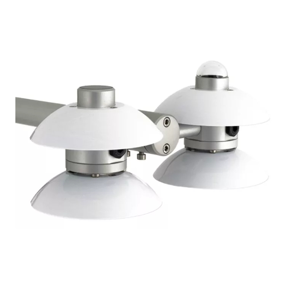
NR01 Four-Component Net Radiation Sensor Overview The NR01 is a four-component net-radiometer consisting of two pyranometers of type SR01, two pyrgeometers of type IR01, a heater, and a PT100 temperature sensor. The pyranometer measures solar radiation (short wave or SW) and the pyrgeometer measures far infrared (long wave or LW) radiation. -
Page 9: Specifications
From these also parameter like SW albedo, sky temperature, (ground) surface temperature and off course net radiation (net value of all SW and LW fluxes) can be calculated. The NR01 requires leveling; a two-axis leveling facility is incorporated in the design. See Section 6, Installation (p. 7) The NR01 is supplied with four separate instrument sensitivities. -
Page 10: General Specifications
Separate outputs of short wave and long wave infrared radiation for better accuracy and more thorough quality assurance • Robust—only requiring limited maintenance Compatible with Campbell Scientific CRBasic data loggers: CR6 • series, CR1000, CR1000X series, CR3000, CR5000, and CR9000(X). The CR1000X, CR1000, and CR9000(X) require the 4WPB100 PRT Bridge Module to measure the internal RTD. -
Page 11: Pyranometer Specifications
NR01 Four-Component Net Radiation Sensor TABLE 5-2. Pyranometer Specifications Sensor Hukseflux thermopile pyranometer Overall classification according to Second class pyranometer ISO 9060 / WMO Response time for 95 % response 18 s Zero offset a (response to 200 W/m < 15 W/m... -
Page 12: Pyrgeometer Specifications
NR01 Four-Component Net Radiation Sensor TABLE 5-3. Pyrgeometer Specifications Sensor IR01 pyrgeometer Overall classification according Not applicable to ISO / WMO Response time for 95 % response 18 s Window heating offset (response < 15 W/m to 1000 W/m net thermal... -
Page 13: Installation
A level is located under the radiation screens. Mounting The NR01 has a hole suitable for a 1-inch IPS pipe (33 mm diameter) for mounting the NR01 onto a CM204 or CM206 crossarm. The crossarm can be mounted to any pole with a 25-mm to 54-mm outer diameter. However, for most applications, Campbell Scientific recommends attaching the crossarm to a CM310-series pole so that the sensor is above vegetation. -
Page 14: Data Logger Wiring
6.3.1 Cable 1 Connections The NR01 has two cables. Cable 1 connects the four radiation outputs to either differential or single-ended terminals on the data logger (TABLE 6-2). A differential voltage measurement is recommended because it has better noise rejection than a single-ended measurement. -
Page 15: Cable 2 Connections
NR01 Four-Component Net Radiation Sensor TABLE 6-2. Cable 1 Wire Color, Function, and Data Logger Connection Data Logger Data Logger Wire Color Description Single-Ended Measurement Differential Measurement U configured for single-ended U configured for differential high Pyranometer Up analog input... -
Page 16: 4Wpb100 Module
NR01 Four-Component Net Radiation Sensor FIGURE 6-2. 4WPB100 Module NOTE The PT100 sensor can be measured by using a 3WHB10K terminal input module instead of the 4WPB100, with only a slight loss of accuracy. This only requires one differential terminal. -
Page 17: Using The Heater
, provides an example CR3000 Program that Controls the Heater (p. A-6) CR3000 program that controls the NR01 heater. Installation of the Radiation Shields Use a hex-head wrench (bolt size 2.0 mm) to install or remove the radiation shield (FIGURE 6-3). Radiation shields are beneficial for instrument... -
Page 18: Data Logger Programming
6.6.1 Pyranometer/Pyrgeometer Measurements The NR01 outputs four voltages that typically range from 0 to 50 mV for the SR01 pyranometers, and ±5 mV for the IR01 pyrgeometer. These voltages are measured by using either the VoltDiff() CRBasic instruction or VoltSE() CRBasic instruction. -
Page 19: Instrument-Inversion Test
Deviations within ±10% can be tolerated. For optimal testing of pyrgeometers, the test should be repeated on a clear night. Operation Measurement Principle The NR01 typically measures net-radiation. The four components of net radiation are measured, and the net radiation is calculated: NOTE The temperature (T ) for the following formula is in Kelvin. -
Page 20: Pyranometers
NR01 Four-Component Net Radiation Sensor = (LW /5.67.10 7-10 7.1.1 Pyranometers A pyranometer measures the solar or SW radiation flux from a field of view of 180 degrees. The atmospheric SW radiation spectrum extends roughly from 300 to 2800 nm. The pyranometer should cover that spectrum with a spectral sensitivity that is as flat as possible. -
Page 21: Pyrgeometers
7-11 pyrano, up pyrano, up In case of the NR01, the pyranometer is type SR01. This is a second-class pyranometer according to the WMO and ISO classification system (ISO 9060). The atmospheric solar radiation consists of two components—direct radiation (in a beam from the sun) and diffuse radiation from the sky. -
Page 22: Spectral Response Of The Pyrgeometer Compared To The Atmospheric
(emission coefficient of 1). For example, equation 7-13 calculates, in Kelvin, the sky temperature: = (LW /5.67.10 7-13 The NR01 pyrgeometers are type IR01. Pyrgeometers are not classified by the ISO or WMO. -
Page 23: Expected Measurement Results
NR01 Four-Component Net Radiation Sensor The atmospheric LW radiation essentially consists of two components: Low temperature radiation from the universe, filtered by the atmosphere. The atmosphere is transparent for this radiation in the so-called atmospheric window (around 10 to 15 micrometer wavelength). -
Page 24: Expected Nr01 Outputs
At night, dew deposition may affect the downward facing pyrgeometer output. In that case, the signal may drop to 0 W/m producing a maximum error of +100 W/m . Campbell Scientific recommends activating the heater to avoid dew deposition. During the day, the window-heating offset may affect the downward facing pyrgeometer output. This can produce a... -
Page 25: Maintenance And Troubleshooting
NR01 Four-Component Net Radiation Sensor Maintenance and Troubleshooting Maintenance The NR01 requires little maintenance. Dirt should be cleaned off the domes every few weeks. Usually errors in functionality appear as unreasonably large or small measured values. See TABLE for specific maintenance recommendations. -
Page 26: Troubleshooting For The Nr01
NR01 Four-Component Net Radiation Sensor TABLE 8-2. Troubleshooting for the NR01 Typically, an error is due to either a short circuit or an open connection. Both can be detected by impedance / The sensor does resistance measurements at the cable end. -
Page 27: Example Programs
Avg SR01 Up (short wave radiation) Avg SR01 Down (short wave radiation) Avg IR01 Up (long wave radiation) Avg IR01 Down (long wave radiation) Avg NR01 temperature (degrees C) Avg NR01 temperature (degrees K) Avg Net shortwave radiation Avg Net long wave radiation... - Page 28 Clear Shield Ensure that it is cable 1 before connecting. Ensure that it is cable 2 before connecting. Jumper to ⏚ with user supplied wire. CRBasic Example A-1. CR1000X Program Measuring NR01 'CR1000X 'Declare Variables and Units Public Batt_Volt Public...
-
Page 29: Cr3000 Program Using Differential Terminals (No 4Wpb100
'Default Data Logger Battery Voltage measurement Batt_Volt: Battery(Batt_Volt) 'NR01 Net Radiometer measurements SR01Up, SR01Dn, IR01Up, IR01Dn, NR01TC, NR01TK, 'NetRs, NetRl, Albedo, UpTot, DnTot, NetTot, IR01UpCo, and IR01DnCo 'For the CR1000X, use autorange for the SR01 measurements due to the wide dynamic range... - Page 30 Avg SR01 Up (shortwave radiation) Avg SR01 Down (shortwave radiation) Avg IR01 Up (longwave radiation) Avg IR01 Down (longwave radiation) Avg NR01 temperature (degrees C) Avg NR01 temperature (degrees K) Avg Net shortwave radiation Avg Net longwave radiation Avg Albedo...
- Page 31 'Define Data Tables DataTable(Hourly,True,-1) DataInterval(0,60,Min,10) Average(1,SR01Up,FP2,False) Average(1,SR01Dn,FP2,False) Average(1,IR01Up,FP2,False) Average(1,IR01Dn,FP2,False) Average(1,NR01TC,FP2,False) Average(1,NR01TK,FP2,False) Average(1,NetRs,FP2,False) Average(1,NetRl,FP2,False) Average(1,Albedo,FP2,False) Average(1,UpTot,FP2,False) Average(1,DnTot,FP2,False) Average(1,NetTot,FP2,False) Average(1,IR01UpCo,FP2,False) Average(1,IR01DnCo,FP2,False) EndTable 'Main Program BeginProg Scan(1,Sec,1,0) 'Default Data Logger Battery Voltage measurement Batt_Volt: Battery(Batt_Volt) 'NR01 Net Radiometer measurements SR01Up, SR01Dn, IR01Up, IR01Dn, NR01TC, NR01TK,...
-
Page 32: Cr3000 Program That Controls The Heater
A.3 CR3000 Program that Controls the Heater This program applies power to the NR01 heater by using the SW12V relay controller and the pulse width modulation instruction (PWM ()). The program uses dewpoint as a set point for the heater. The CR3000 calculates dewpoint by using the relative humidity (RH) measurements provided by the EE181 Temperature/Relative Humidity Probe. - Page 33 Appendix A. Example Programs TABLE A-3. Sensor Wiring for Heater Control Example Program NR01 SW12V Cable 1 Cable 2 Wire EE181 Wire Color Wire Color Color Terminal Wire Color Description CR3000 Pyranometer Up Signal Pyranometer Up Blue Reference Pyranometer Down...
- Page 34 Appendix A. Example Programs CRBasic Example A-3. CR3000 Program Measuring NR01 and Controlling Heater 'CR3000 Series Datalogger PipeLineMode '*** Constants *** Const NR01_SHORT_DW_CAL = 1000/13.41 'Unique NR 01 shortwave downwelling multiplier (1000/15.5). Const NR01_SHORT_UW_CAL = 1000/13.93 'Unique NR 01 shortwave upwelling multiplier (1000/13.5).
- Page 35 Appendix A. Example Programs Sample (1,t_hmp_mean,IEEE4) Sample (1,e_hmp_mean,IEEE4) Sample (1,rh_hmp_mean,IEEE4) Sample (1,t_dew_hmp_mean,IEEE4) Sample (1,duty_cycle,IEEE4) Average (9,Rn,IEEE4,FALSE) EndTable DataTable (scratch,TRUE,1) TableHide DataInterval (0,5,Min,10) Average (1,t_hmp,IEEE4,FALSE) Average (1,e_hmp,IEEE4,FALSE) Average (1,e_sat_hmp,IEEE4,FALSE) EndTable BeginProg Scan (1,Sec,0,0) 'Control the net radiometer heater. (duty_cycle,4,250,mSec) 'Data logger panel temperature. PanelTemp (panel_temp,250) 'Measure battery voltage.
- Page 36 Appendix A. Example Programs duty_cycle = 1 Case Is < ( set_point_temperature+DELTA_SET_POINT_1 ) duty_cycle = MAX_DUTY_CYCLE_1+(t_nr01-(t_dew_hmp_mean+273.15))*SLOPE_1 Case Is < ( set_point_temperature+DELTA_SET_POINT_1+DELTA_SET_POINT_2 ) duty_cycle = MAX_DUTY_CYCLE_2+(t_nr01-(t_dew_hmp_mean+273.15+DELTA_SET_POINT_1))*SLOPE_2 Case Else duty_cycle = 0.01 EndSelect Else duty_cycle = 0.01 EndIf EndIf CallTable (stats) NextScan EndProg A-10...
-
Page 37: Cable Details
Appendix B. Cable Details TABLE provides the polarity and PCB04 connection for Cable 1 (solar), and TABLE provides the polarity and PCB04 connection for Cable 2 (PT100). TABLE shows the internal connections to the terminal blocks, which should only be required for servicing such as cable replacement. TABLE B-1. -
Page 38: Internal Electrical Diagram Of The Nr01 (For Servicing Purposes Only
Appendix B. Cable Details TABLE B-3. Internal Electrical Diagram of the NR01 (for servicing purposes only) PCB04 PCB04 PCB05 PCB05 Connection Terminal Connection Terminal Polarity Pyrgeometer – Pyrgeometer Pyrgeometer – DOWN Pyrgeometer DOWN Pyranometer Pyranometer – Pyranometer DOWN Pyranometer –... - Page 39 Campbell Scientific Worldwide Offices Australia Germany Location: Garbutt, QLD Australia Location: Bremen, Germany Email: Email: info@campbellsci.com.au info@campbellsci.de Website: www.campbellsci.com.au Website: www.campbellsci.de Brazil South Africa Location: São Paulo, SP Brazil Location: Stellenbosch, South Africa Email: andread@campbellsci.com.br Email: sales@csafrica.co.za Website: Website: www.campbellsci.com.br www.campbellscientific.co.za...
Need help?
Do you have a question about the NR01 and is the answer not in the manual?
Questions and answers