Campbell CS215 Instruction Manual
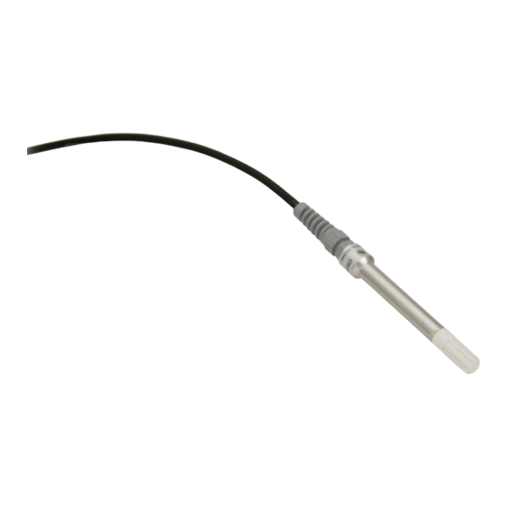
Temperature and
relative humidity probe
Hide thumbs
Also See for CS215:
- Instruction manual (38 pages) ,
- Instruction manual (40 pages) ,
- Instruction manual (44 pages)

Related Manuals for Campbell CS215


Summary of Contents for Campbell CS215
- Page 1 CS215 Temperature and Relative Humidity Probe Revision: 4/18 C o p y r i g h t © 2 0 0 5 - 2 0 1 8 C a m p b e l l S c i e n t i f i c ,...
- Page 3 Limited Warranty “Products manufactured by CSI are warranted by CSI to be free from defects in materials and workmanship under normal use and service for twelve months from the date of shipment unless otherwise specified in the corresponding product manual. (Product manuals are available for review online at www.campbellsci.com.) Products not manufactured by CSI, but that are resold by CSI, are warranted only to the limits extended by the original manufacturer.
- Page 4 Campbell Scientific company serves your country. To obtain a Returned Materials Authorization (RMA) number, contact CAMPBELL SCIENTIFIC, INC., phone (435) 227-9000. Please write the issued RMA number clearly on the outside of the shipping container. Campbell Scientific’s shipping address is: CAMPBELL SCIENTIFIC, INC.
- Page 5 Periodically (at least yearly) check electrical ground connections. • WHILE EVERY ATTEMPT IS MADE TO EMBODY THE HIGHEST DEGREE OF SAFETY IN ALL CAMPBELL SCIENTIFIC PRODUCTS, THE CUSTOMER ASSUMES ALL RISK FROM ANY INJURY RESULTING FROM IMPROPER INSTALLATION, USE, OR MAINTENANCE OF TRIPODS, TOWERS, OR ATTACHMENTS TO TRIPODS AND TOWERS SUCH AS SENSORS, CROSSARMS, ENCLOSURES, ANTENNAS, ETC.
-
Page 7: Table Of Contents
Table of Contents PDF viewers: These page numbers refer to the printed version of this document. Use the PDF reader bookmarks tab for links to specific sections. 1. Introduction ..............1 2. Precautions ..............1 3. Initial Inspection ............1 4. - Page 8 7-1. CS215 and 41303-5A Radiation Shield (left) and RAD06 Radiation Shield (right) on a tripod mast ......... 8 7-2. CS215 and 41303-5A Radiation Shield on a CM200 Series Crossarm ..................9 9-1. Correct fit of sensor element (side view)........... 14 9-2.
- Page 9 Table of Contents D-3. Example aC! Sequence ..............D-5 CRBasic Examples B-1. CR1000X Program for Measuring the CS215 ......... B-1 B-2. CR200(X) Program for Measuring the CS215 ......... B-2...
-
Page 11: Introduction
Short Cut is an easy way to program your datalogger to measure the CS215 sensor and assign datalogger wiring terminals. Short Cut is available as a download on www.campbellsci.com. It is included in installations of LoggerNet, PC200W, PC400, or RTDAQ. - Page 12 Celsius. This can be changed by clicking the Deg C box and selecting Deg F, for degrees Fahrenheit, or K for Kelvin. SDI-12 Address defaults to 0. Type the correct SDI-12 Address for the CS215 if it has been changed from the factory-set default value. After entering the Properties, click on the Wiring tab to see how the sensor is to be wired to the datalogger.
-
Page 13: Overview
Overview The CS215 probe uses a single chip element that incorporates both a temperature and an RH sensor. Each element is individually calibrated with the calibration corrections stored on the chip. The element is easily changed in the field, reducing downtime and calibration costs. -
Page 14: Specifications
CS215 Temperature and Relative Humidity Probe An inner expanded PTFE filter minimizes the effects of dust and dirt on the sensor. The filter is lightweight and hydrophobic, thereby diminishing its effect on the time response of the sensor. The probe housing is designed to withstand permanent exposure to all weather and to fit into a range of radiation shields, including compact shields. -
Page 15: Relative Humidity Measurement
CS215 Temperature and Relative Humidity Probe Relative Humidity Measurement Operating Range: 0 to 100% RH (–20 to 60 °C; see Appendix C, Environmental Performance (p. C-1) Accuracy at 25 °C: ±2% over 10 to 90% ±4% over 0 to 100% Short-Term Hysteresis: <1% RH... -
Page 16: Datalogger Programming
(p. B-1) SDI12Recorder() Instruction The SDI12Recorder() measurement instruction programs CRBasic dataloggers to measure the CS215 sensor. This instruction sends a request to the sensor to make a measurement and then retrieves the measurement from the sensor. See Section 8.1, Sensor Measurement , for more information. -
Page 17: Installation In A 41303-5A Or 41303-5B 6-Plate Shield
(p. 15) discuss temperature and relative humidity sensors. When used in the field, the CS215 must be housed in a radiation shield. Typically, the 41303-5A or RAD06 six-plate solar radiation shield is used. A 41003-5 or RAD10 ten-plate solar radiation shield can also house the CS215 sensor. -
Page 18: Installation In A 41003-5 Or 41003-5A 10-Plate Shield Using 6637 Collar Adapter
Collar Adapter Loosely thread the collar adapter into the base of the 10-plate shield. Insert the CS215 sensor through the collar as far as it will go. Hold the collar and sensor, and finish threading the collar into the shield by hand. -
Page 19: Operation
Operation Sensor Measurement The CS215 sensor responds to the ?!, M!, MC!, C!, CC!, R!, and RC! SDI-12 commands. For the ?! command, the sensor returns the SDI-12 address. For the other commands, the sensor returns two values: temperature in degrees Celsius and relative humidity as a percentage (0 to 100). -
Page 20: Measurements At Fast Scan Rates
In low-power applications, conserve battery power by turning the 12 V supply to the CS215 on just before the measurement (allowing a warm-up time of at least 100 ms) and then turning it off afterwards. If available, the switched 12 V... -
Page 21: Measuring Multiple Sdi-12 Sensors
Multiple SDI-12 sensors can be connected to a single datalogger control terminal if they have unique SDI-12 addresses. The CS215 can have an SDI-12 address of 0 to 9. Some SDI-12 devices can have an SDI-12 address of 0 to 9, A to Z, or a to z. -
Page 22: Calibration
Replacing the element should return the CS215 to factory calibration for temperature and relative humidity. Sensor Element Replacement Procedure Wash your hands to avoid getting dirt or grease on the element. - Page 23 CS215 Temperature and Relative Humidity Probe CAUTION An incorrectly oriented element will not work, will draw excessive power, and may be damaged if left powered in this state for more than a few seconds. Grasp the body of the sensor (this also ensures you are at the same electrical potential as the element) and, holding the black tip of the element between your fingertips, pull the element out of the socket.
-
Page 24: Correct Fit Of Sensor Element (Side View)
CS215 Temperature and Relative Humidity Probe Gold colored Sensing part of side of the tip the element. Printing on this side. Sensing Element Gold pins Sensor Thread for the connector filter sticking out of the end of the tube Center line of... -
Page 25: Attributions And References
CS215 Temperature and Relative Humidity Probe Sensing part of element NOT on the center line Center line of the sensor body FIGURE 9-2. Incorrect fit of sensor element (side view) 10. Attributions and References Santoprene ® is a registered trademark of Exxon Mobile Corporation. - Page 26 CS215 Temperature and Relative Humidity Probe Meyer, S. J. and K. G. Hubbard, 1992: Nonfederal Automated Weather Stations and Networks in the United States and Canada: A Preliminary Survey, Bulletin Am. Meteor. Soc., 73, No. 4, 449-457. Weiss, A., 1977: Algorithms for the calculation of moist air properties on a hand calculator, Amer.
-
Page 27: Importing Short Cut Code Into Crbasic Editor
Appendix A. Importing Short Cut Code Into CRBasic Editor This tutorial shows: How to import a Short Cut program into a program editor for • additional refinement How to import a wiring diagram from Short Cut into the comments of •... -
Page 29: Example Programs
This CR1000X program can be adapted for use with CR300-, CR6-, and CR800-series, CR1000, CR3000, and CR5000 dataloggers. CRBasic Example B-1. CR1000X Program for Measuring the CS215 'Program measures one CS215 sensor every 5 seconds and stores the average 'temperature and a sample of relative humidity every 10 minutes. 'Wiring Diagram... - Page 30 Appendix B. Example Programs This example program shows the measurement of a single CS215 and can be used directly with CR200(X) series dataloggers. CRBasic Example B-2. CR200(X) Program for Measuring the CS215 'CR200(X) Series Datalogger 'Program measures one CS215 sensor every 30 seconds and stores the average 'temperature and a sample of relative humidity every 10 minutes.
-
Page 31: Environmental Performance
Appendix C. Environmental Performance This Appendix details tests and limitations of the sensor when exposed to extremes of the environment. C.1 Tests to Defined Standards The sensor element has been tested by the manufacturer and found to comply with various environmental test standards as shown in TABLE below: TABLE C-1. -
Page 32: Operating Range Of Rh Element
World Meteorological Organization. If an RH value is required to be referenced to ice, the CS215 readings will need to be corrected. One consequence of using water as the reference is that the maximum humidity... -
Page 33: Sdi-12 Sensor Support
Only three wires are necessary — serial data, ground, and 12 V. With unique addresses, multiple SDI-12 sensors can connect to a single SDI-12 terminal on a Campbell Scientific datalogger. This appendix discusses the structure of SDI-12 commands and the process of querying SDI-12 sensors. -
Page 34: Acknowledge Active Command (A
Appendix D. SDI-12 Sensor Support TABLE D-1. Campbell Scientific Sensor SDI-12 Command and Response Set Name Command Response Start Concurrent atttnn<CR><LF> Measurement aC1!...aC9! Start Concurrent aCC! Measurement and atttnn<CR><LF> aCC1!...aCC9! Request CRC a<values><CR><LF> Send Data aD0!...aD9! a<values><CRC><CR><LF> Continuous aR0!...aR9! a<values><CR><LF>... -
Page 35: Start Verification Command (Av
Appendix D. SDI-12 Sensor Support D.2.3 Start Verification Command (aV!) The response to a Start Verification command can may include hardware diagnostics, but like the aI! command, the response is not standardized. Command: aV! Response: atttn<CR><LF> a = sensor address ttt = time, in seconds, until verification information is available n = the number of values to be returned when one or more subsequent D! commands are issued... -
Page 36: Start Concurrent Measurement Commands (Ac
Appendix D. SDI-12 Sensor Support TABLE D-2. Example aM! Sequence The datalogger makes a request to sensor 0 to start a measurement. Sensor 0 immediately indicates that it will return 2 00352<CR><LF> values within the next 35 seconds. Within 35 seconds, sensor 0 indicates that it has completed the measurement by sending a service 0<CR><LF>... -
Page 37: D-3. Example Ac! Sequence
Appendix D. SDI-12 Sensor Support TABLE D-3. Example aC! Sequence The datalogger makes a request to sensor X to start a concurrent measurement. Sensor X immediately indicates that it will have 5 (05) values ready for X03005<CR><LF> collection within the next 30 (030) seconds. -
Page 38: Start Measurement Commands With Cyclic Redundancy Check (Amc! And Acc
Appendix D. SDI-12 Sensor Support D.2.8 Start Measurement Commands with Cyclic Redundancy Check (aMC! and aCC!) Error checking is done by using measurement commands with cyclic redundancy checks (aMC! or aCC!). This is most commonly implemented when long cable lengths or electronic noise may impact measurement transmission to the datalogger. -
Page 39: Continuous Measurement Command (Ar0
Transparent mode is entered while the computer is communicating with the datalogger through a terminal emulator program. It is accessed through Campbell Scientific datalogger support software or other terminal emulator programs. Datalogger keyboards and displays cannot be used. The terminal emulator is accessed by navigating to the Datalogger menu in PC200W, the Tools menu in PC400, or the Datalogger menu in the Connect screen of LoggerNet. -
Page 40: Cr1000 Example Of Using The Sdi-12 Transparent Mode To
Appendix D. SDI-12 Sensor Support At the Select SDI12 Port prompt, type the number corresponding to the control port where the sensor is connected and press Enter. The response Entering SDI12 Terminal indicates that the sensor is ready to accept SDI- 12 commands. -
Page 41: Cr200(X) Example Of Using The Sdi-12 Transparent Mode To Change The Sdi-12 Address From 0
Appendix D. SDI-12 Sensor Support Select All Caps Mode. Press Enter until the datalogger responds with the CR2XX> prompt. Type SDI12 and press Enter. The response SDI12> indicates that the sensor is ready to accept SDI-12 commands. To query the sensor for its current SDI-12 address, type ?! and press Enter. The sensor responds with its SDI-12 address. - Page 44 Campbell Scientific Worldwide Offices Australia Germany Location: Garbutt, QLD Australia Location: Bremen, Germany Email: Email: info@campbellsci.com.au info@campbellsci.de Website: www.campbellsci.com.au Website: www.campbellsci.de Brazil South Africa Location: São Paulo, SP Brazil Location: Stellenbosch, South Africa Email: andread@campbellsci.com.br Email: sales@csafrica.co.za Website: Website: www.campbellsci.com.br www.campbellscientific.co.za...
Need help?
Do you have a question about the CS215 and is the answer not in the manual?
Questions and answers