
Related Manuals for Campbell CS125


Summary of Contents for Campbell CS125
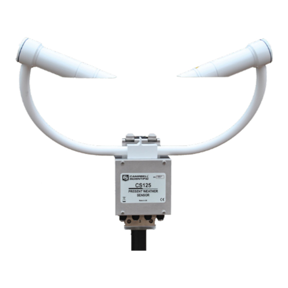
- Page 1 CS125 Present Weather Sensor Revision: 10/15 C o p y r i g h t © 2 0 1 3 - 2 0 1 5 C a m p b e l l S c i e n t i f i c ,...
- Page 3 Limited Warranty “Products manufactured by CSI are warranted by CSI to be free from defects in materials and workmanship under normal use and service for twelve months from the date of shipment unless otherwise specified in the corresponding product manual. (Product manuals are available for review online at www.campbellsci.com.) Products not manufactured by CSI, but that are resold by CSI, are warranted only to the limits extended by the original manufacturer.
- Page 4 SCIENTIFIC, INC., phone (435) 227-9000. After an application engineer determines the nature of the problem, an RMA number will be issued. Please write this number clearly on the outside of the shipping container. Campbell Scientific’s shipping address is: CAMPBELL SCIENTIFIC, INC.
- Page 5 • Periodically (at least yearly) check electrical ground connections. WHILE EVERY ATTEMPT IS MADE TO EMBODY THE HIGHEST DEGREE OF SAFETY IN ALL CAMPBELL SCIENTIFIC PRODUCTS, THE CUSTOMER ASSUMES ALL RISK FROM ANY INJURY RESULTING FROM IMPROPER INSTALLATION, USE, OR MAINTENANCE OF TRIPODS, TOWERS, OR ATTACHMENTS TO TRIPODS AND TOWERS SUCH AS SENSORS, CROSSARMS, ENCLOSURES, ANTENNAS, ETC.
-
Page 7: Table Of Contents
7.2 Mounting the CS125 ................. 9 7.3 Optional Campbell Scientific Mount ............10 8. CS125 internal connectors’ description ....12 8.1 CS125 recommended wiring using Campbell Scientific cables ..... 14 9. CS215 T/RH Sensor ..........15 10. Functions of the internal switches ......16 11. - Page 8 12. Interface methods – Device Configuration Utility/Command line/Menu ........27 12.1 Configuring a PC for talking to the CS125 ........... 28 13. Definition of the variables that can be set by the user on the CS125 ......... 28 14. Command line mode..........30 14.1 The SET command ................
- Page 9 9-2 Connection for an external CS215 temperature and RH sensor connected to a CS125................. 17 16-1 Calibration disk ..................42 16-2 Mounting calibration disk ..............44 17-1 CS125 DevConfig download instructions ..........46 17-2 CS125 DevConfig screen when OS update is complete ....... 46...
-
Page 11: Introduction
The CS125 uses the well-established forward scatter system for visibility measurement, utilising a 42º scatter angle. The CS125 uses high speed sampling to reduce missed events such as rain and hail and improves response to other suddenly changing conditions. -
Page 12: General Safety
These should be followed carefully in order to gain the maximum benefit from the use of this product. 1.2 Sensor Unit Safety The CS125 sensor has been checked for safety before leaving the factory and contains no internally replaceable or modifiable parts. WARNING Do not modify the CS125 unit. -
Page 13: Technical Specification
User Guide 2. Technical specification Minimum Nominal Maximum Value Value Value Visibility characteristics Reported Visibility (metric) 10 metres 75,000 metres Reported Visibility (imperial) 33 feet 246,062 feet/ 46 miles Visibility accuracy up to 10,000 m +/-10% Visibility accuracy up to 15,000 m +/-15% Visibility accuracy above 15,000 m +/-20%... -
Page 14: Supported Data Rates For Rs232 And Rs485
(5) Each hood takes 30W, 60W is the total for both hoods on the sensor together. (6) The ground of the CS125 and the ground of any RS485 equipment cannot be further apart than this voltage. The CS125 ground (pin 1) on connector B, see page 12, can be connected to the ground of the host equipment. -
Page 15: Environmental Specifications
Hood heater Turn Off >15°C Extended temperature ranges are only guaranteed if the sensor has been tested by Campbell Scientific and verified within this temperature range. Some degradation of absolute accuracy can be expected at the extremes of the extended ranges. -
Page 16: Mechanical Specifications
7. Installation procedure The CS125 measures environmental variables and is designed to be located in harsh weather conditions. However there are a few considerations to take into account if accurate and representative data from a site are to be obtained. - Page 17 (unless the analysis of microclimate weather is being sought). The CS125 has good resistance to background light but it is a good idea to avoid locations where the transmitter is pointing at a light scattering or reflecting surface.
-
Page 18: Equipment Grounding
The CS125 must be properly grounded. It is sufficient to ground the mounting bracket and if the CS125 is connected to a grounded metal mast, and in electrical contact with it, then this will be sufficient. Otherwise, the mounting bracket should be earthed and a grounding boss is supplied to allow this. -
Page 19: Mounting The Cs125
Only tighten the nuts to a degree necessary to hold the CS125 firmly in place. Where the CS125 is to be mounted onto another type of mast, please refer to the manual for that mast for mounting details. CAUTION Ensure that the CS125 is mounted according to the figure below. -
Page 20: Optional Campbell Scientific Mount
CS125 Present Weather Sensor 7.3 Optional Campbell Scientific Mount A Campbell Scientific `optical sensor mount’, part number 009354, is available. This will put the sample volume at about 1.5 m in compliance with the WMO `Guide to Meteorological Instruments and Methods of Observation’, 7 Edition, Section 9.3.4. - Page 21 User Guide Drill four 12 mm diameter holes using the mount base as a template or following the drawing below to a depth of 77 mm. Figure 7-5. Mounting footprint Clean the holes of all debris. Place washers and nuts on the ends of the wedge anchors supplied (to protect the threads during installation).
-
Page 22: Cs125 Internal Connectors' Description
CS125 Present Weather Sensor 8. CS125 internal connectors’ description The CS125 has four standard IP66 rated glands. The first gland is by default used by the power/communications line. This comprises the 7-30 V for the main electronics, and the serial communications wires. The CS125 is supplied with 5 m cable already connected. - Page 23 User Guide The configuration cable is fitted with a 9-way D connector for use with a PC serial port or USB to serial adaptor. Connector A - Five way connector Pin number Description Notes Pin 1 +ve supply Main electronics +ve supply input Pin 2 Auxiliary Electronics 0V.
-
Page 24: Cs125 Recommended Wiring Using Campbell Scientific Cables
8.1 CS125 recommended wiring using Campbell Scientific cables (this cable is supplied already connected as standard) The CS125 is provided pre-wired with a default 5 m power and communications cable which is terminated at one end with a 9 pin D-connector (DB9). The D-... -
Page 25: Cs215 T/Rh Sensor
The connections for the CS215 are shown below. The CS215 itself can be mounted in a Met20 screen on the same mast as the CS125. The screen can be mounted on the top section of an OSM1 optical mast below a CS125. -
Page 26: Functions Of The Internal Switches
Figure 9-1. Connection for the optional CS215 T/RH sensors 10. Functions of the internal switches The CS125 is equipped with four switches located within the main enclosure. These switches perform certain functions at power up, their functions are detailed below. -
Page 27: Connection For An External Cs215 Temperature And Rh Sensor
RS232 communication state (38400 bps). This is useful during field tests or maintenance when the CS125 has been remotely configured for RS485 mode or a baud rate your PC does not support. This change is temporary and will not be stored to flash. -
Page 28: Message Formats: A Breakdown Of The Different Default Outputs Of The Cs125 - Basic/Partial/Full
11. Message Formats: A breakdown of the different default outputs of the CS125 – Basic/Partial/Full The CS125 has twelve different message formats available to the user. All parameters are space delimited with a unique start and end character allowing easy storage into any logger (see Section 15 on how to set default outputs). -
Page 29: Messages With Synop Present Weather Codes
User Guide Partial Format, Visibility Only Full Format, Visibility Only 11.2 Messages with SYNOP Present Weather Codes SYNOP Present Weather Basic Format SYNOP Present Weather Partial Format... -
Page 30: Messages With Metar Present Weather Codes
CS125 Present Weather Sensor SYNOP Present Weather Full Format (default) 11.3 Messages with METAR Present Weather Codes METAR Present Weather Basic Format METAR Present Weather Partial Format... -
Page 31: Messages With Generic Synop Present Weather Codes
User Guide METAR Present Weather Full format *Note: relative humidity is only available if a CS215 temperature and RH sensor is attached. If not this field is “-99”. 11.4 Messages with Generic SYNOP Present Weather Codes These messages include simplified, generic present weather codes such as 70 for snow which may be required for some data collection systems. - Page 32 CS125 Present Weather Sensor Generic SYNOP Present Weather Partial format Generic SYNOP Present Weather Full format Message ID break down Definition Basic format. Contains only distance and system information Partial format. Contains user alarm outputs Full format. Contains all system alarms codes...
- Page 33 Ten minute average Note: In accordance with WMO requirements the CS125 produces visibility measurement that are either one or ten minute rolling averages that are updated at the chosen output interval or when the sensor is polled. Those averages are not direct averages of MOR measurements but are averages of extinction coefficient and that average is then used to calculate the MOR for that period.
- Page 34 1 = More particles detected than can be processed. The emitter power level reporting too high will cause the CS125 to shut down and go into low power mode. The severity of the alarm. The higher the number the more serious the error is considered to be.
-
Page 35: Example Cs125 Message Outputs
0 - 100 External relative humidity in %RH (-99 indicates either a fault or no CS215 T/RH sensor is connected) 11.5 Example CS125 message outputs Basic format (visibility only) 0 9 0 6682 M ABCD SYNOP present weather partial format 4 9 0 60 6682 M 0 0 54 4.5 63 20.2 91 ABCD... -
Page 36: Synop Codes Produced By The Cs125
CS125 Present Weather Sensor 11.6 SYNOP Codes produced by the CS125 Weather Type 4680 Code No significant weather observed Haze or smoke, or dust in suspension in the air, visibility ≥ 1 km* Haze or smoke, or dust in suspension in the air, visibility < 1 km*... -
Page 37: Metar Codes Produced By The Cs125
This would be the preferred method of setting up a CS125 if it was connected to a logger for instance. The configuration setting commands can be sent via a logger to the CS125 removing the need for a local PC to set up the unit. -
Page 38: Configuring A Pc For Talking To The Cs125
The CS125 should now be ready to accept commands. It is possible to set the CS125 into the default communication state via one of the internal switches on the CS125 main board. See Section 9. - Page 39 2 = Sample one second in every two 3 = Sample one second in every three etc. Dew heater override 0 = Allow the CS125 to automatically control the dew heaters 1 = Turn the dew heaters off Hood heater override...
-
Page 40: Command Line Mode
POLL command is used to request the current visibility and/or alarm conditions from the sensor. The CS125 can be configured to expect any commands sent to it to include a valid checksum. For simple commands, e.g. GET and POLL, fixed value checksums can be used (see the example programs). -
Page 41: Example Of A Set Command
The only functional difference is that the SETNC command does not commit the values set into flash memory. This means that the next time the CS125 is power cycled it will revert back to its previous settings. This command... -
Page 42: Example Of A Setnc Command
SETNC:0:0 1 1 1000 1 0 15000 2 0 M 60 1 2 0 1 1 0 0 0 1 7 80 :XXXX: 14.3 The GET Command The GET command retrieves settings data from the CS125, including message format data and user alarm settings amongst others. This command does not retrieve visibility or environmental information from the CS125. - Page 43 User Guide User Alarm 2 Distance Serial Baud Rate Sensor serial number (read only) Visibility Units Message interval Polling Or Continuous modes Message Format RS232 or RS485 serial communications enabled Averaging Period Sample timing Dew heater override Hood heater override Dirty window compensation CRC checking on received commands Sensor power down voltage...
-
Page 44: The Poll Command - Polling The Cs125
14.4 The POLL command – Polling the CS125 The POLL command requests the current visibility and/or alarm conditions from the CS125. The output format of this command depends on how the CS125 is configured using the SET command or the menu interfaces. -
Page 45: Entering The Cs125 Menu System
If the setting to check the checksum on received commands is enabled the checksum varies with the Sensor ID value. 15. Entering the CS125 menu system The user can enter the menu system by typing ‘open id’ into their terminal program then pressing the return key on their keyboard. - Page 46 No changes will take effect until you `Exit and Save’. The exception to this is the calibration menu, but you will be informed before any changes are made. Typing `1’ opens the message menu containing settings relating to the CS125’s outputs. Menu 1: The message output menu...
- Page 47 `FEET’ and typing `4’ will allow the message interval to be entered. Option (2) allows the User Alarms to be set, again by toggling through options or changing values. Menu 2: The user alarm menu CS125 ALARM - MENU 2 ID 0 S/N 1009 (1) Toggle user alarm one: DISABLED...
- Page 48 (0) Return to main menu -> Consult the ‘calibration’ section of this manual for information on how to calibrate the CS125 present weather sensor. NOTE Once a calibration is finished changes are immediate, but factory calibrations can be restored if needed using Option `(2)’ in the calibration menu.
- Page 49 User Guide Menu 4: The system information menu CS125 INFORMATION - MENU 4 ID 0 S/N 1003 OS version: 007646v1 Alarm Value - Last visibility reading: 3258M - Overall system status: No faults - Emitter dirty window alarm: - Emitter internal temperature: 38.4...
- Page 50 CRC checking. In addition it allows the sensor power down voltage to be set. If set this will shut down the CS125 before the battery voltage has fallen low enough to damage a back-up battery. The RH threshold can also be set from this menu.
-
Page 51: Calibrating The Cs125
010815. The calibration must be run using the onboard menu system. If you have Campbell Scientific’s Device configuration program a terminal emulation screen is provided in the CS125 screens to let you access this function. To perform the calibration you will need a CS125 calibrator disk and a computer with a standard serial port compatible with the CS125. - Page 52 Do you want to perform a calibration Y/N? Once you have started the tests you will be asked for the CS125 calibrator serial number and coefficient with a confirmation at each step giving you the chance to correct typing mistakes.
- Page 53 Press any key once this is done. Remove the bungs once the sensor instructs you to. Place the CS125 calibrator into the volume by fastening it to the central mounting point. At this stage it is advisable to clean the lenses. Refer to Section 18 NOTE `Cleaning’...
-
Page 54: Dirty Window Zero Calibration
CS125 Present Weather Sensor Figure 16-2. Mounting calibration disk Starting light level calibration. This test will take approximately two minutes. This part of the test will take approximately two minutes. Every ten seconds a dot should appear indicating that the test is progressing as normal. -
Page 55: Performing A Firmware Update
Typing ‘3’ returns text similar to the following: - Current values EO=3200 DO=4649 DD=995 Cal DW offset? Y/N? Then type ‘Y’. The CS125 responds in a similar way to the following: - Calibrating dirty window system...Please wait DD=990 DO=4535 DD=1000 DO=4531... -
Page 56: Cs125 Devconfig Download Instructions
CS125 Present Weather Sensor Figure 17-1. CS125 DevConfig download instructions Figure 17-2. CS125 DevConfig screen when OS update is complete... -
Page 57: Cleaning
Campbell Scientific if required. Only general cleaning of the lenses is required to keep the sensor working efficiently. Cleaning of the CS125 will be required from time to time to ensure that the lenses are free from contaminants. The frequency of required cleaning depends on the exposure of the instrument to such contaminants. -
Page 58: Lubricating The Enclosure Screws
CS125 Present Weather Sensor 19. Lubricating the enclosure screws The CS125 enclosure screws should be lubricated with a suitable anti-seize grease (often copper loaded) to protect the threads from corrosion. This should be reapplied when resealing the enclosure at regular intervals, normally after replacing the desiccant. - Page 59 User Guide After the bags of desiccant have been allowed to cool in an airtight desiccator, they may be removed and placed in either an appropriate type polyliner tightly sealed to prevent moisture adsorption, or a container that prevents moisture from coming into contact with the regenerated desiccant. Some care should be taken when re-activating desiccant bags.
-
Page 61: Cs125 Block Diagram
Appendix A. CS125 block diagram Power level + 850nm Photo- Transimpedance Driver circuitry Emitter detector amplifier Amplifier Emitter power Amplifier and filter feedback and filter Dirty window Dirty window detector detector Hood temperature Second stage amplifiers and filters 14-bit Analogue to... - Page 62 CS125 Present Weather Sensor...
-
Page 63: Example C Code Of The Ccitt Crc
Appendix B. Example C code of the CCITT The code below is provided as an example for programmers implementing their own code to communicate with the sensor. Users using Campbell loggers can use the Checksum command in CRBasic to generate a CCITT checksum. Command: Checksum/ChkSumString,1,0). - Page 64 CS125 Present Weather Sensor...
-
Page 65: Example Crbasic Programs
Alias SerialIndest(24)=SYNOP_code Alias SerialIndest(25)=Temperature 'deg C Alias SerialIndest(26)=Relative_Humidity '%, 0..100 Alias SerialIndest(27) = checksumrx 'CCITT Checksum 'Define the serial port to which the CS125 is connected - amend as needed Const CS125_Comport = COM1 'Main Program BeginProg 'Open the logger serial port to which the CS125 is connected... - Page 66 CS125 Present Weather Sensor SerialInRecord(CS125_Comport,InString,&h02,0,&h03,NBytesReturned,01) 'Check that a message has been recieved first If NBytesReturned > 0 Then 'Split out the Data into strings SplitStr (SerialIndest(),InString," ",27,5) 'Check the received checksum is valid 'Calculate the expected checksum lngCRCCalc = CheckSum(InString,1,NBytesReturned-5) 'Extract the checksum from the message &...
- Page 67 Alias SerialIndest(26)=Relative_Humidity '%, 0..100 Alias SerialIndest(27) = checksumrx 'CCITT Checksum 'Define the serial port to which the CS125 is connected - amend as needed Const CS125_Comport = COM1 'Preload the poll command for a sensor for address 0, in this example 'If the sensor has a different address uncomment the relevant line Const CS125_Poll = CHR(2)&"POLL:0:0:3A3B:"&CHR(3)&CHR(13) 'address 0...
- Page 68 CS125 Present Weather Sensor 'Const CS125_Poll = CHR(2)&"POLL:8:0:939A:"&CHR(3)&CHR(13) 'address 8 'Const CS125_Poll = CHR(2)&"POLL:9:0:A4AA:"&CHR(3)&CHR(13) 'address 9 'Main Program BeginProg 'Open the logger serial port to which the CS125 is connected SerialOpen (CS125_Comport,38400,3,0,1000) Scan(10,Sec,1,0) 'The sensor is polled every 10 seconds SerialOut(CS125_Comport,CS125_Poll,"",0,100) SerialInRecord(CS125_Comport,InString,&h02,0,&h03,NBytesReturned,01)
- Page 69 '------------------------------------------------------------------------------- ' CS125 Visibility ' Program to test the SET command part of the command line interface on the CS125 ' Do not run this script for extended periods of time (days!) as it writes ' to flash over and over and will eventually wear the flash out...
- Page 70 CS125 Present Weather Sensor CheckVal = CheckSum (TempStringFunc,1,0) ' Use the CCITT CRC16 checksum ' Create final string going out to CS125 including start characters and end characters CS125CommandString = CHR(2) + TempStringFunc + ":" + FormatLong (CheckVal,"%04X") + ":" + CHR(3) + CHR(13) + CHR(10)
- Page 71 '------------------------------------------------------------------------------- ' CS125 Visibility ' Program to test the SETNC command part of the command line interface on the CS125 ' This command does not commit the settings to flash so settings will be lost if ' the sensor is power cycled ' This example uses a CS215 temperature and humidity probe to determine dew point.
- Page 72 ' Create a check sum of the values going out CheckVal = CheckSum (TempStringFunc,1,0) ' Use the CCITT CRC16 checksum ' Create final string going out to CS125 including start characters and end characters CS125CommandString = CHR(2) + TempStringFunc + ":" + FormatLong (CheckVal,"%04X") + ":"...
- Page 73 Appendix C. Example CRBasic programs 'CS215 Temperature & Relative Humidity Sensor measurements AirTC and RH SDI12Recorder(TRHData(),5,"0","M!",1,0) 'Calculate DewPoint DewPoint(TempDewPoint,AirTC,RH) ' Gather the current settings from the CS125 SerialFlush (Com1) TempString = "GET:0:0" CheckVal = CheckSum (TempString,1,0) ' Use the CCITT CRC16 checksum OutString = CHR(2) + TempString + ":"...
- Page 74 C.5 Example CRBasic GET program '------------------------------------------------------------------------------- ' CS125 Visibility ' Program to test the GET command part of the command line interface on the CS125 ' Connecting to serial port one on a CR1000 logger ' Logger:CR1000 ' Example outputs including checksums (varies with sensor ID)
- Page 76 Santo Domingo, Heredia 40305 SOUTH AFRICA COSTA RICA • cleroux@csafrica.co.za • info@campbellsci.cc www.campbellsci.co.za www.campbellsci.cc Campbell Scientific Southeast Asia Co., Ltd. Campbell Scientific Ltd. 877/22 Nirvana@Work, Rama 9 Road Campbell Park Suan Luang Subdistrict, Suan Luang District 80 Hathern Road Bangkok 10250...